Description:
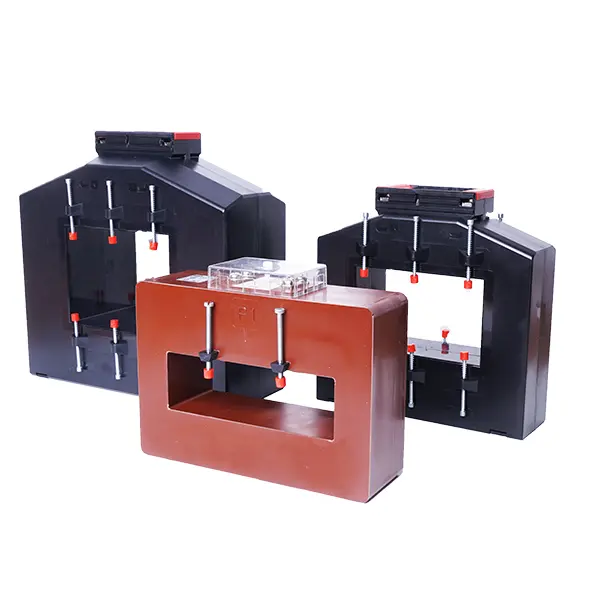
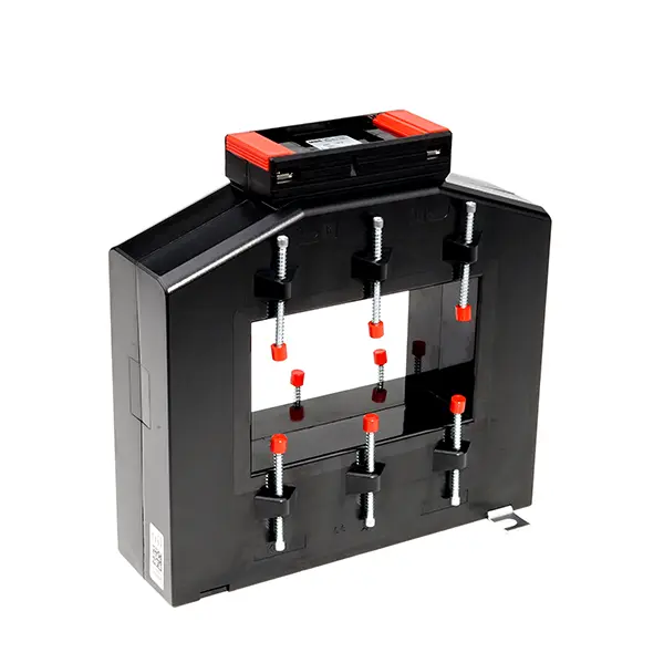
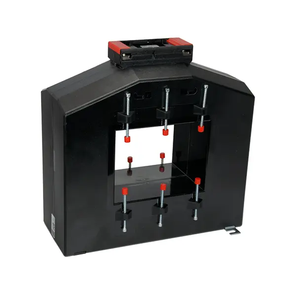
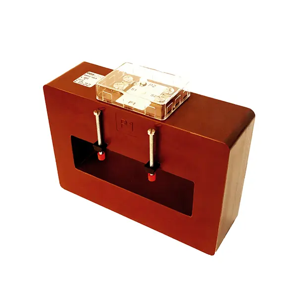
External field compensated current transformers for high primary currents
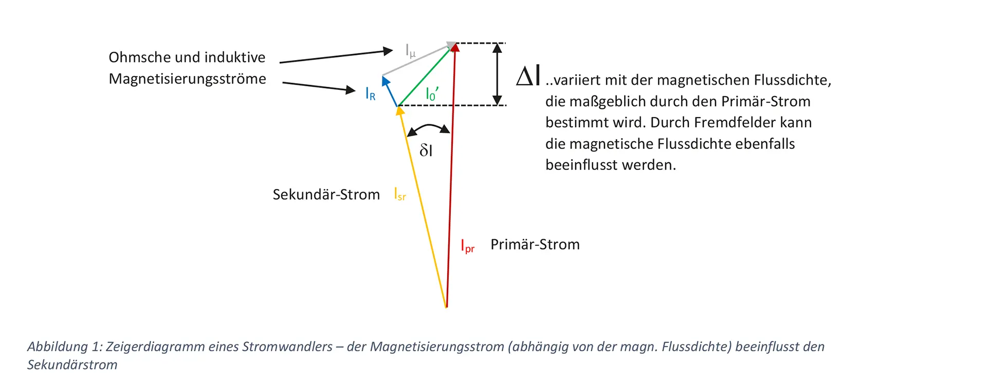
When current transformers are used in high-current applications of approx. 2500 A and above, the strength of the magnetic field of the adjacent primary conductors can become so significant that this must be taken into account in the design of the current transformers. Magnetic fields from adjacent phases or N conductors can influence the magnetic flux density in the current transformer. The magnetic flux density, which changes due to external influences, can sometimes have a significant effect on the error values of the current transformers.
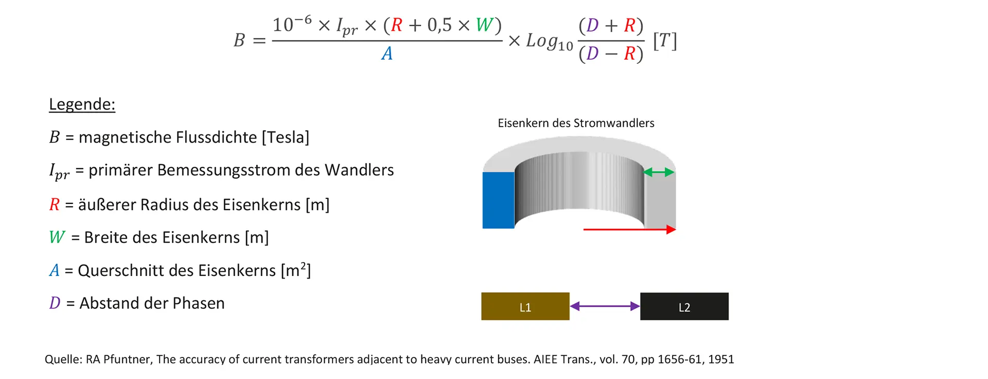
The following formula provides a practical way of estimating the influence on the magnetic flux density:
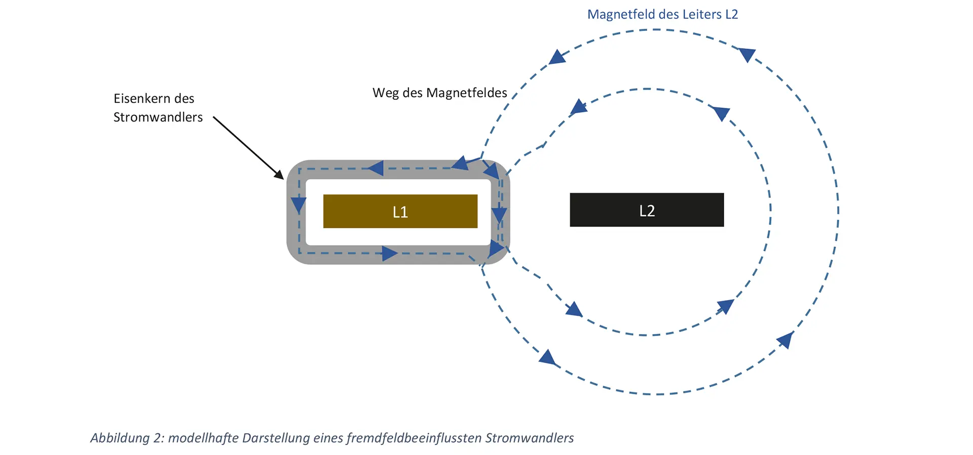
The following illustration clearly shows how the magnetic field of conductor L2 can change the magnetic flux in the iron core of the current transformer of conductor L1. Like electricity, magnetic field lines also seek the path of least resistance. Despite the longer path through the core, the highly permeable iron cores offer less magnetic resistance to the magnetic field lines of conductor L2. A current transformer mounted around conductor L2 could significantly minimize the influence of conductor L2 on conductor L1.
In order to guarantee the accuracy class specified on the rating plate even in critical high-current measurements, MBS AG offers external field-compensated current transformers for high-current applications. For this purpose, the current transformers are manufactured using a special winding technique that can virtually eliminate the influence of external fields from neighboring or return conductors.

In the first solution, in addition to the required secondary windings, four segments are applied to the wound core. The individual segments are cross-connected with the diametrically opposite segments. This circuit counteracts one-sided magnetic flux densities caused by external fields. This prevents any influence on the measurement accuracy. In the laboratory, external field influences were reduced by approx. 80%. One disadvantage is the considerable effort required in production. The additional winding and the resulting size of the current transformer also often represent a decisive disadvantage for the customer.
In several test series at MBS AG, the secondary winding was wound in several segments and then connected in parallel. The external fields could be compensated similarly well. The winding order can be used.
The positive results were verified in extensive laboratory tests. A wide variety of conductor arrangements were tested.

The external field compensated current transformers are currently available in the following designs.
End of content
End of content