Due to the many advantages of power electronics, the return to linear loads is almost impossible. Rather, it is to be expected that harmonic loads in European networks will continue to increase as a result of the expansion of alternative energy sources and the increase in non – linear consumers.
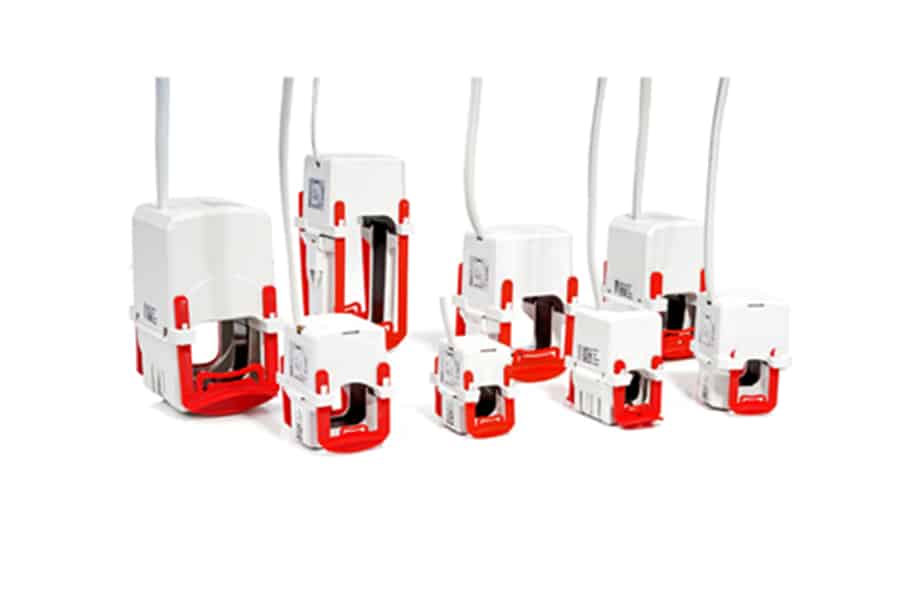
For measurement up to 20kHz, MBS AG offers the complete Series of XCTB, XKBU and XKBR. These ranges of current transformers guarantee high-precision transmission up to 20kHz and is thermally designed for use in harmonic-loaded networks.
…..with us, you are always one step ahead!
New measuring requirements for inductive current transformers in the low-voltage range
Changes to the structure of generation and consumption
Over the last few years, the proportion of renewable energy in Germany has grown massively. Wind, biomass, photovoltaic and hydroelectric plants now make up approximately 30% of the country’s energy mix.
Unlike in conventional nuclear or coal-fired power stations, where all synchronous generators are used to produce electricity, here inverters or frequency converters are used. As such, it is not always possible to achieve a clean sine wave.
The distortions are caused by the switching semiconductor elements in the inverter. Harmonics generated in this way are whole multiples of the first harmonic and can extend far into the single-digit kilohertz range. The total harmonic distortion (THD) factor specifies the undesirable distortion ratio of the 50 Hz sinusoidal oscillation and regularly reaches between 10 and 30%.
In addition to the harmonics produced by inverters on the generator side, there have also been changes on the consumer side in recent years. Non-linear consumers such as LED or energy-saving lamps are pushing linear ones, like traditional incandescent bulbs, out of our daily lives almost completely.
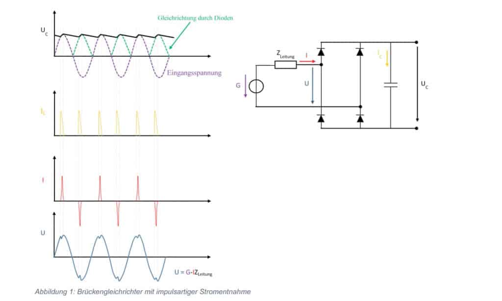
Plug-in power supply units for mobile phones and laptops are no longer made from small transformers either, but from semiconductor circuits known as switched-mode power supplies. It would not be possible to create such small, light power supply units any other way. But these benefits are set against one big disadvantage: the current is drawn from the public grid not as a sinusoidal waveform, but in pulses. The figure below illustrates this:

The filter capacitor shown in the diagram not only smooths the required output voltage, it is also recharged in pulses by the rectifier diodes. These steep current peaks generate reactive power on the one hand, and harmonics on the other.
Standards regulate limit values – but not always!
There is already a corresponding set of international norms that limits harmonic currents in end devices with a power consumption > 75 W. Devices under 75 W are not currently covered by standards. In the interests of keeping costs down, manufacturers do not usually implement filter measures or complex power factor correction. The EN 61000-3-2 set of standards does not come into play until the 25 W mark for lamps either; for example, where energy-saving lamps are concerned, THDI values of 30 to 70% and higher are not uncommon during warm-up and in continuous duty. It should also be noted that, even when they do kick in, the standards only define limit values up to 2 kHz. As a result, manufacturers have hardly taken interference suppression into account at all when developing electronic products for the frequency range > 2 kHz in the past.
In addition, more and more electrical motors with variable-frequency drive technology are being used in the industrial sector. Today already, the percentage of electrical motors sold that have a frequency-controlled drive stands at around 40%. The majority of these motors utilise pulse width modulation technology, which can generate THDI values in the range from 100 to 120%. Clean sine waves are almost impossible to identify at these values.

Power electronics have so many benefits that we can categorically state there will be no return to linear consumers such as the traditional incandescent bulb. In fact, we can expect harmonic loads to increase even further in European grids, due to the development of alternative sources of energy and the growth of non-linear consumers. We should also bear in mind that having lots of consumers that are not regulated by standards could cause considerable interference overall.
Filter systems have already had to be installed in office buildings where just computers, telephone systems and energy-efficient bulbs are used, in order to bring problems with harmonics under control.
Effects of harmonics
Grid operators are primarily interested in the economic effects of harmonics. When it comes to harmonic currents, the most important phenomena are as follows :
- Overloading of neutral conductors
- Overheating of transformers
- False tripping of circuit breakers/miniature circuit breakers
- Overstressing of power-factor correction capacitors
- Skin effects
If the distortion level in the supply voltage reaches a value > 10%, this shortens the lifetime of devices considerably. This reduction is estimated as follows:
- 32.5% for 1-phase machines
- 18% for 3-phase machines
- 5% for transformers.
To maintain the lifetime expected from the nominal load, the devices named above must be over-dimensioned.
Standard regulation for distribution network operators
The latest draft of VDE-AR-N 4100 deals with this matter. Point 5.4.4.3 of this regulation refers to harmonic currents of up to 9 kHz that need to be monitored and covers not only generating plants, but also receiving plants and storage systems. The customer should liaise with the grid operator and take action to reduce harmonic currents – particularly by constructing filter circuits. In future we can assume, therefore, that current measurements up to 9 kHz will be taken continuously across the whole low-voltage network.
Looking at the overall picture of the rise in distributed energy generation plants and non-linear consumers, we can see this is a very sensible move. Grid operators and their customers will need measuring equipment that can accurately record harmonic currents of up to 9 kHz.
Current transformers up to 20 kHz
MBS AG offers the full series of XCTB current transformers for measurements up to 20 kHz. These products guarantee high-precision transmission up to 20 kHz on the one hand, and are designed to withstand the thermal demands of running in networks subject to harmonics on the other.
Output signals are 1 or 5 A, just like with the familiar inductive current transformer to IEC 61869-2. Performance data corresponds to standard values too. As a result, these transformers can also be used in conventional 50 Hz applications. An additional rating plate defines the frequency transmission behaviour.
