
Residual current measuring with „DACT“
Damage to the electrical insulation (reduction of the insulation resistance) can lead to personal injury. For this reason, residual current devices (RCDs) are installed in many systems all over the world in order to prevent human injury. The most popular RCD is a residual current circuit breaker (RCCB), these devices have a defined tripping range of approx. 15 to 30 mA in Germany.
Besides this RCCB there is a further safety test of the insulation resistance of the system as a repetition test according to the
DIN VDE 0105 part 100. This test ensures that the system complies with safety regulations and installation standards. This measurement can only be performed on a voltage-free system. The test should be performed every four years.
Due to financial aspects, shorter test intervals are not preferred, even if the plant has already aged considerably. Nevertheless, in order to detect signs of degeneration in the insulation system of the system at an early stage and thus counteract an unplanned shutdown, a differential current measurement is recommended.
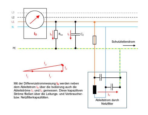
With this method even very low fault currents can be detected, which can be the cause of the degenerating insulation. In addition to these fault currents, there are other phenomena that complicate matters somewhat. For example, in addition to the fault current or the system-typical ohmic leakage current, various capacitive leakage currents are measured which cannot provide information about the insulation status of the system.
These leakage currents are often generated by machines operated with electric motors. In the large winding capacity of the motor to the laminated core and thus to the housing, capacitive leakage currents can flow, which can significantly increase when operating with frequency converters. These capacitive leakage currents can even cause damage to the engine bearings. The capacity of long motor cables also leads to leakage currents across the screen. These leakage currents have the consequence that often a residual current beyond 30 mA is measured.
Despite these difficulties, it is often possible to detect some tendency in the differential current. This can be used as a sign for an early repeat check according to the DIN VDE 0105 part 100.
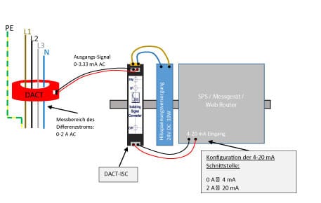
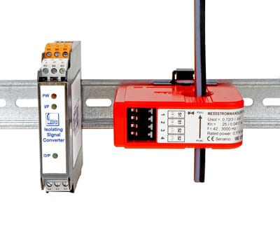
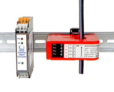
The differential current measurement is performed with the residual current transformer DACT which is compatible with some universal energy meters. In order to have a very flexible standard output signal of 4-20 mA you can use the DACT-ISC which converts the AC output signal of the DACT into the DC standard signal. In addition, there is the possibility to connect a relay.
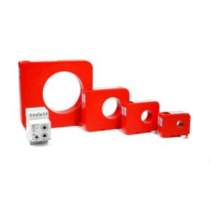
Core balance transformers type A; series „DACT“
for detection of residual currents in 3- / 4-wire AC systems
Application
Our core balance transformers of series DACT were designed in connection with our earth fault relay DACT-ELR and the residual current converter DACT-ISC, for the detection of residual currents (earth fault currents), type A.
In combination with our earth fault relay DACT-ELR it is possible to detect residual currents in two ranges from 0.02 … 2A and
0.25 … 25 A.
The residual current converter DACT-ISC converts the signal supplied by the core balance transformer into the standard signal
4 … 20 mA.
- Features / benefits of core balance transformer Technical details of core balance transformer
- High-sensitive current sensor for detecting even – Operating temperature: -10°C < T < +70°C
- smallest fault currents – Storage temperature: -25°C < T < +70°C
- Easy connection by means of 4-pin – Max. operating voltage: 800 V
- WAGO® cage clamp – Nominal surge voltage: 8 kV
- Mounting onto 35mm DIN-rail by means of snap-on – Pollution degree: III
- mounting (except DACT 120) – Protection class: Housing: IP 40; Terminals: IP 20
- High security due to integrated overvoltage – Frequency range: 30 Hz … 3 kHz
- protection – Applicable technical standards: IEC 60664-1 / IEC 60664-3
- Suitable for flexible applications because of a wide frequency range
Residual current converter „DACT-ISC“
for converting residual currents into the standard signal 4…20 mA DC

Application
The input impedance of the residual current converter is matching with the electrical design of the core balance transformer DACT and converts the output signal of the core balance
transformer into the standard signal of 4…20 mA DC. In combination with the residual current transformer DACT it is possible to measure residual currents up to 2 A AC. This current is transformed by the DACT with the factor of 600.

Description
The working range of the residual current transformer DACT is specified up to 25 A with a burden between 80 and 100 Ω. If higher currents occur, the DACT goes into saturation and blocks higher currents over 25 A. Therefore, the electronic circuits of the residual current converter DACT-ISC are safe.
For operation the residual current converter DACT-ISC requires a separate auxiliary voltage supply with 20-56 V DC.
A LED on the device indicates, if the auxiliary supply is present. Additionally the device has two further LEDs, which are used to control the correct function. They indicate if the input signal resp. the output signal is present (starting approx. at 5% of full input / output range).
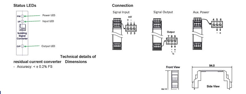
Technical details of residual current converter Dimensions
– Accuracy: < ± 0.2% FS
– Response time: < 250 mSec.
– Output ripple: < ± 0.1% FS
– Input impedance: 90 Ω (± 10%)
– Output impedance: 4…20mA, 520 Ω
– Power consumption: max. 4W (DC), 6VA (AC)
– Operating frequency: 30 Hz … 750 Hz
– Operating temperature: -0°C < T < +60°C
– Humidity: 20 … 95%, non-condensing
– Temperature coefficient: ± 100 PPM / °C
– Test voltages: 2kV AC / 1 min., Auxiliary power against
input / output / housing
– Applicable technical standards: IEC 61010 (category 3)
– EMC: EN 55011:2002; EN 61326:2003

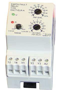
Earth fault relay „DACT-ELR“
for detection of residual currents from 0.02 … 2 A and 0.25 … 25 A
Application
The earth fault relay DACT-ELR was developed in combination with our core balance
transformers of series DACT and are designed for the detection of residual currents. It has two switchable measuring ranges from 0.02 … 2 A and 0.25 … 25 A.
Not only the measuring range can be switched, but also the tripping delay can be adjusted from 0.1 – 10 seconds.
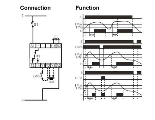
Mode of operation
On connection of the earth fault relay to the auxiliary voltage supply, the green LED illuminates and signals the operational readiness.
When exceeding the set earth fault level and after the adjustable tripping time has elapsed, the output relay energises. The exceedance of the set earth fault level and the empowerment of the relay is signalled by the red LED on the device.
Depending on the connection the relay has a auto reset. The DACT-ELR has a fixed hysteresis of 5% of the set value, should the earth fault level fall below the set value less 5%, the output relay will de-energise and the red LED will extinguish.
However, should the optional latch facility be utilised between terminals Y1 and Y2 via a remote NC contact, the NC contact has to be opened or the auxiliary voltage supply removed to reset the relay (manual reset).
Additional to that the relay has via terminals Y2 and Y3 a remote test input operated by a NO contact for function control.
Features / benefits of earth fault relay Technical details of earth fault relay
– 2 earth fault ranges 0.02…2A + 0.25…25A – Auxiliary supply: AC: 400V; 230V; 110V; 48V; 24V (50/60Hz; ±15%)
– Fixed hysteresis at 5% DC: 48V; 24V (± 15%)
– Latching facility (manual or auto reset) – Galvanic isolation: AC versions: yes; DC versions: no*
– Additional function control of the relay *via integrated DC-DC converter optional with galvanic isolation
– LED display of switching status – Power consumption: max. 3 VA
– Adjustable tripping delay from 0.1 to 10 sec. – Input impedance: 100 Ω
– Easy mounting on DIN-rail possible – Hysteresis: Fixed at 5% of set value (other values on request)
– Tripping delay: Adjustable 0.1 … 10 sec.; (0…+30%)
– Repeat accuracy: ± 2% (at constant ambient) … ±5% (VDE 0435)
– Operating temperature: -10°C < T < +65°C
– Response time: 100 mSec. on make; 200 mSec. on break
– Max. power (output relay): 2200VA (AC) / 30 W (DC)
– Max. switching voltage (output relay): 250V (AC/DC)
– Max. switching current (output relay): 10A (AC) / 1A (DC)
– Mechanical life: approx. 30×106 ops (max. 600 ops / hr)
– Electrical life: 200.000 at 2200VA (resistive)
– Connection terminals: screws for cross-section 0.08…2.5mm2
– Housing material: Polycarbonate, auto extinguishable acc. UL 94 V-0
– Applicable techn. standards:
EN 61000-6-1: 2007
EN 61000-6-3: 2007
EN 61010-1: 2002
2014/35/EU