Winding Current Transformers in Low Voltage
In practice it is often necessary to measure currents in the nominal current range below 100 A. However, since most of the measuring devices used for current measurement only have 1/5 A measuring inputs, a maximum current of 5 A can be measured directly with the measuring device. In order to be able to measure currents between 5 and 100 A, inductive current transformers are usually used. The use of plug-in current transformers is often not possible.
Due to the physical operating principle of current transformers with decreasing primary rated currents, the iron core cross-section required to transmit a certain power increases sharply.
The required core cross-section of a current transformer is calculated as follows.
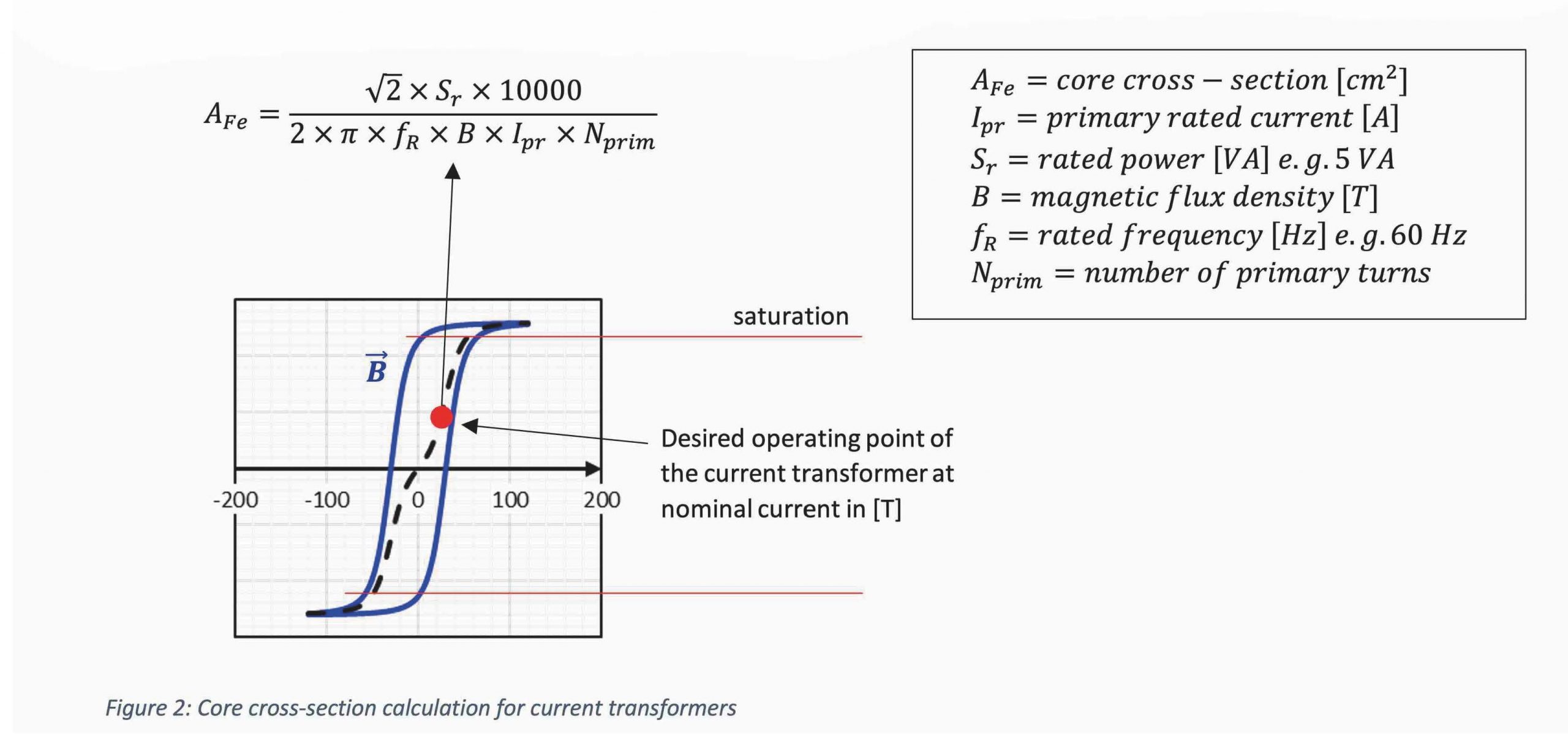
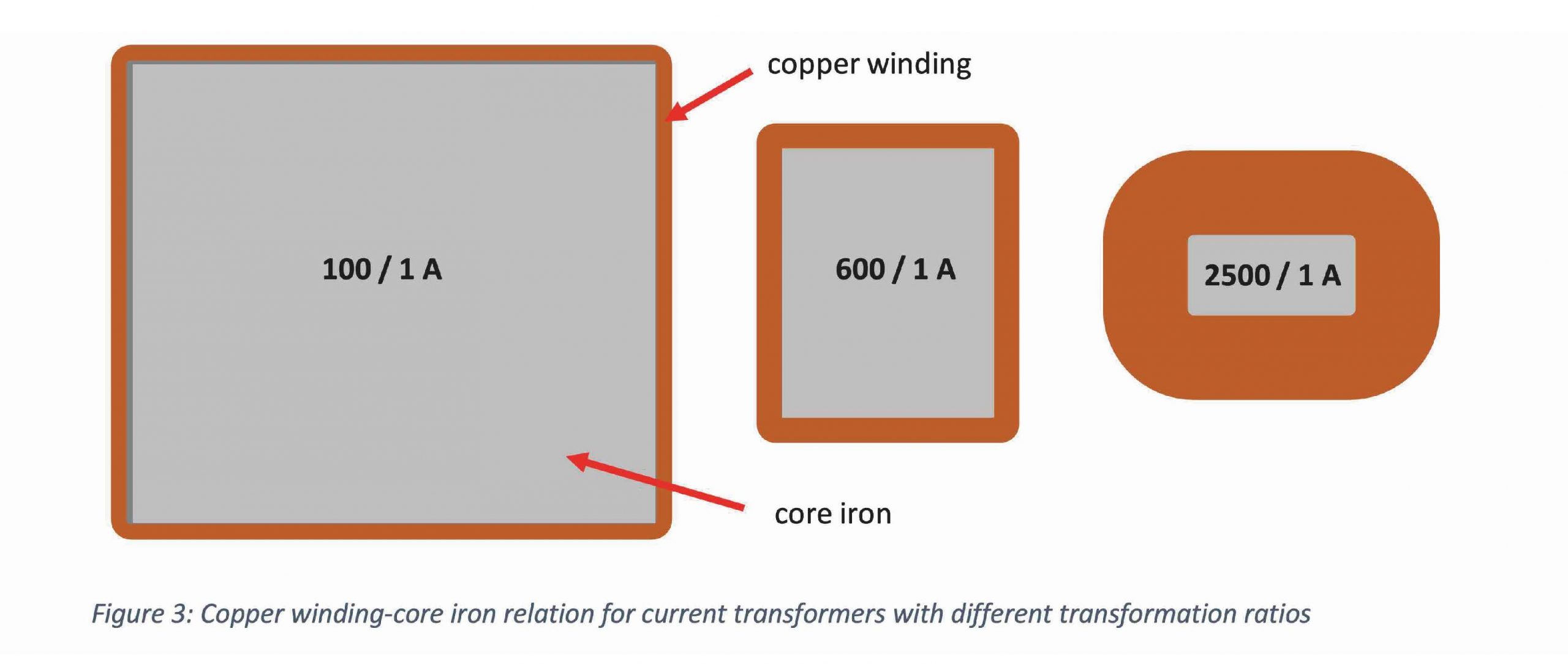
The above formula makes it clear that with the same rated power Sr and the same magnetic flux density B, the core cross-section requirement increases as the primary rated current decreases. This relationship is presented again visually in the following figure.
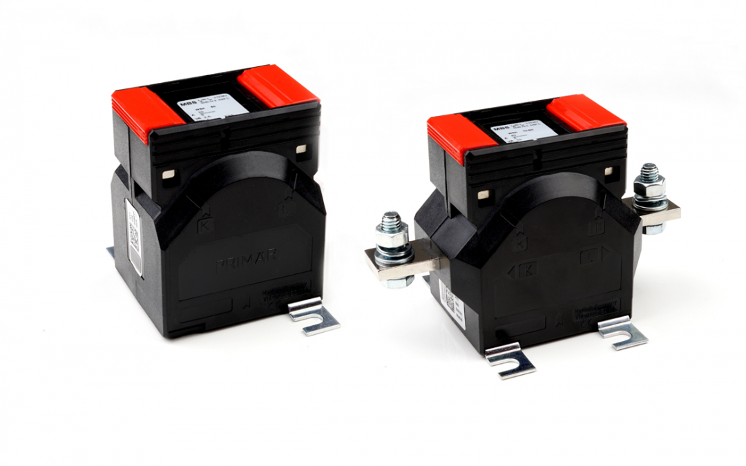
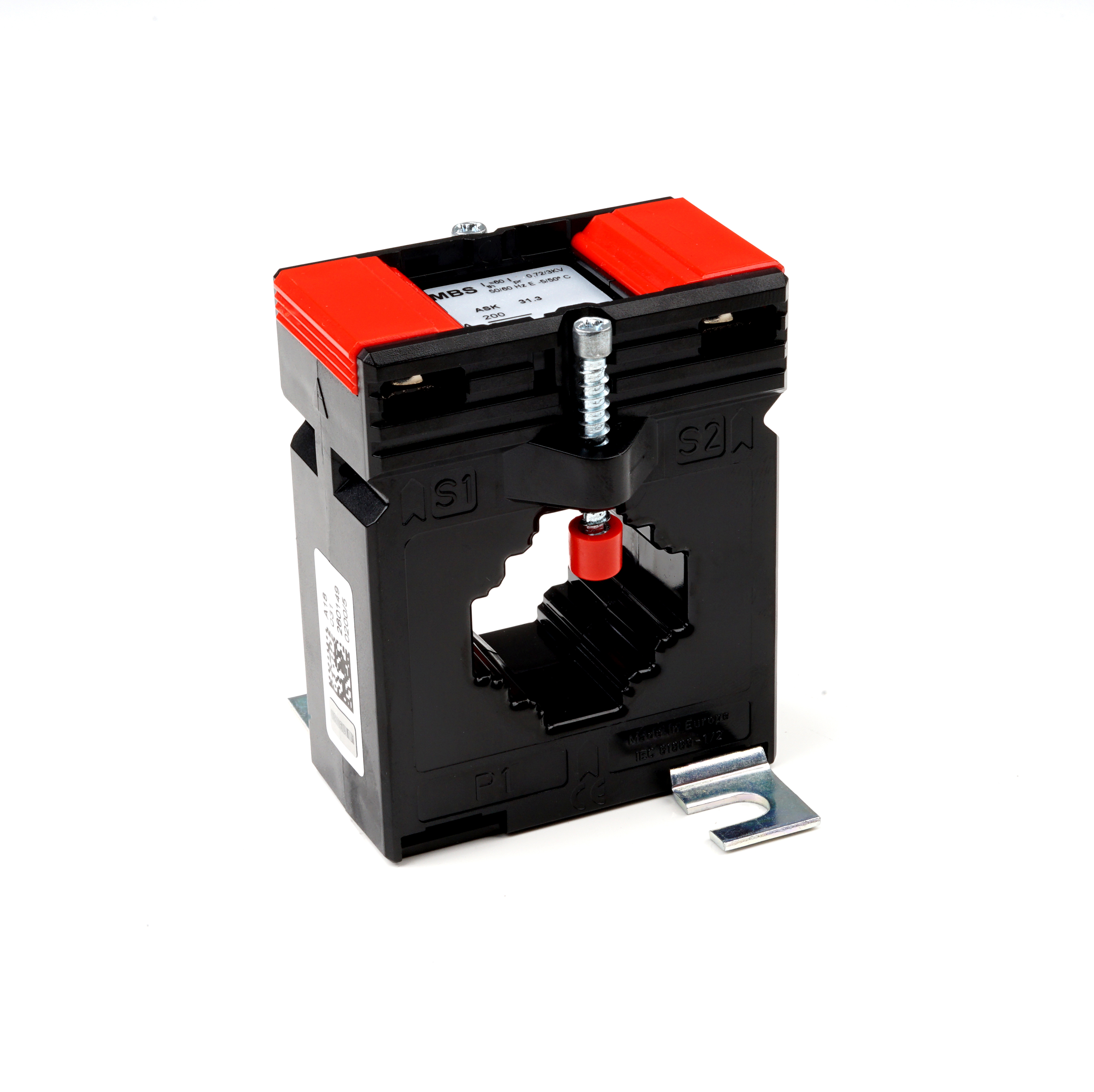
In order to achieve an exact measurement in the specified primary current range with the smallest possible size of the current transformer, so-called winding current transformers are often used here. Winding current transformers do not have a primary conductor bushing, as is usually the case with conventional plug-in current transformers. To install a winding current transformer, it is necessary to separate the primary circuit (load circuit). The ends of the primary conductors are then connected directly to the primary input terminals of the winding current transformer. In order to achieve the desired ratio, the primary conductor is routed around the measuring core inside the converter housing several times.
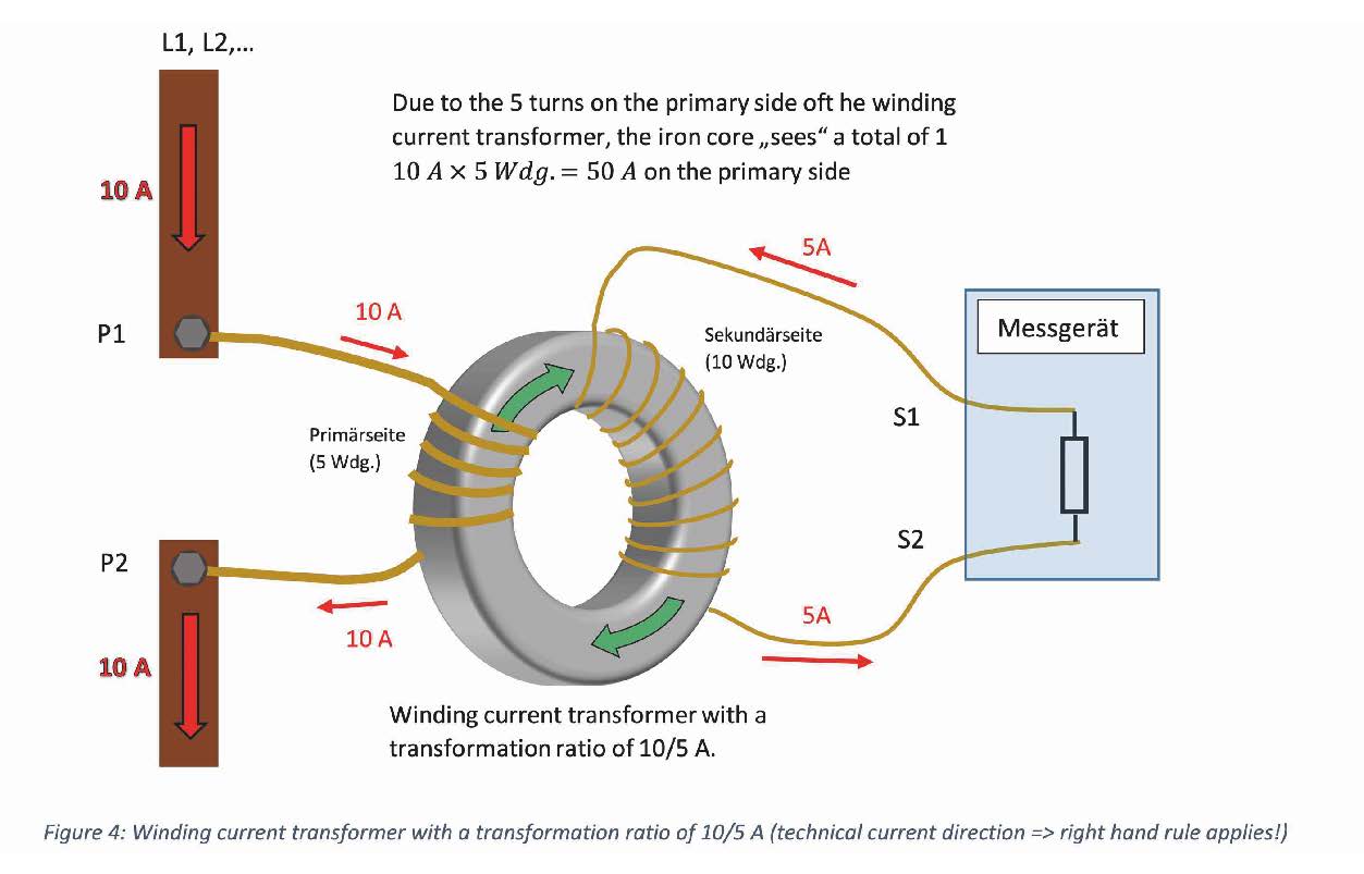
Due to the higher number of primary turns, the required core cross-section can be reduced according to the formula in Figure 2.
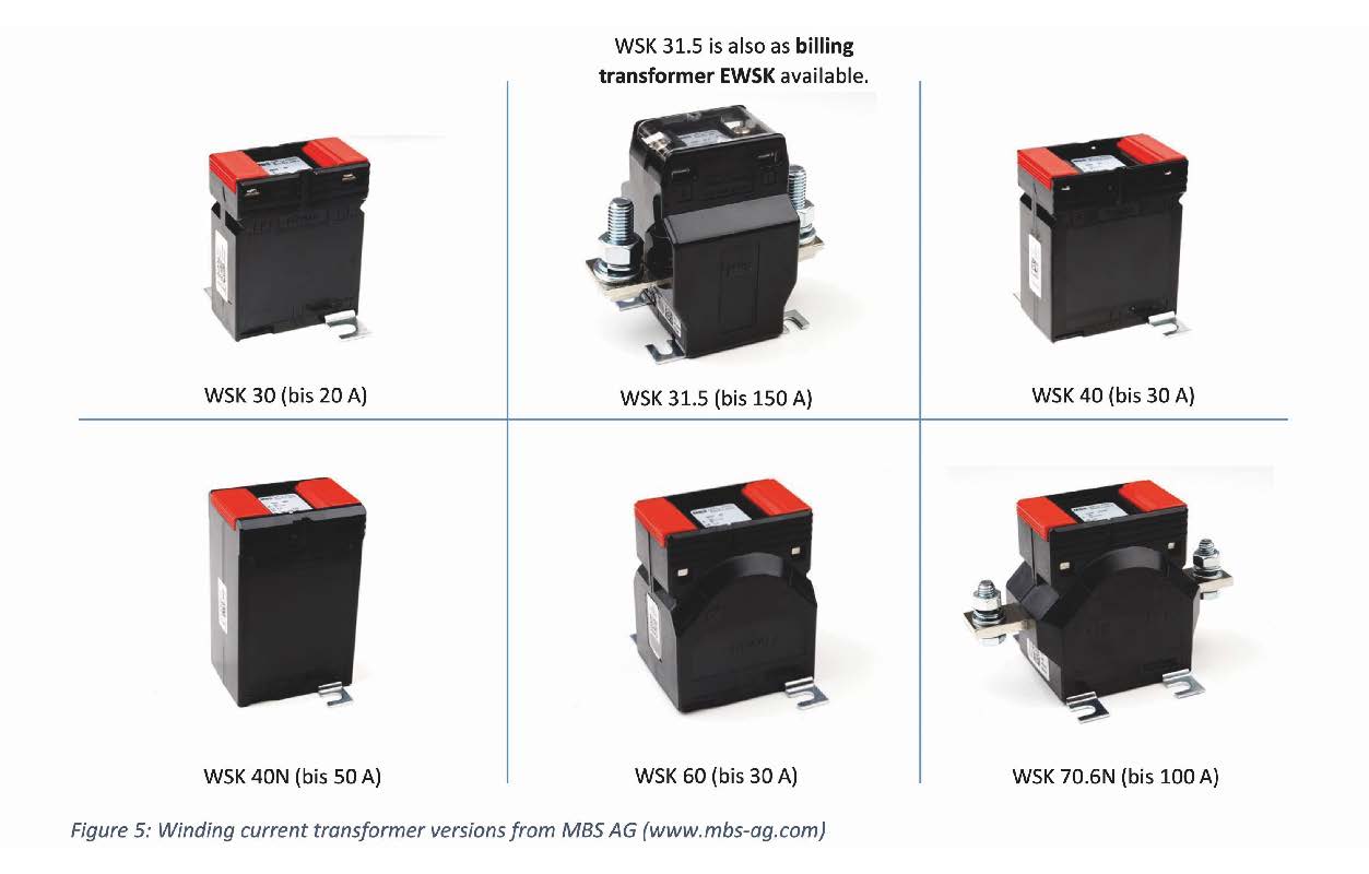
Winding current transformers for low-voltage applications are available from MBS AG up to 150 A in various designs.
o-called current matching transformers are also included in the group of winding current transformers.
Current matching transformers are manufactured for primary rated currents up to approx. 10 A and enable the proportional conversion of the input current to smaller or larger secondary rated currents. If, for example, longer distances from the current transformer to the measuring device have to be bridged, it is advisable to choose the main transformer with a secondary current of 1 instead of 5 A. In this way, line wiring can be minimized.
The following formula should be used to calculate the internal consumption of copper lines.
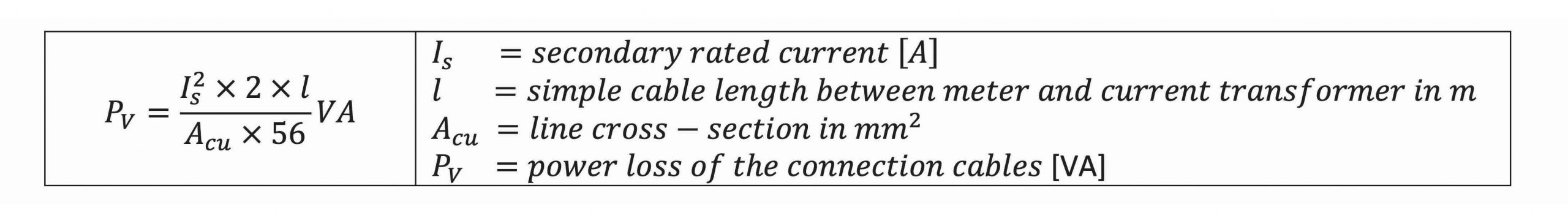
Derived from this formula it can be determined that by halving the original secondary current, a reduction in power losses to 25 % of the original value can be achieved.
Shortly before the measuring device, an current matching transformer could convert the 1 A to 5 A. It should be noted that the accuracy classes of the main and matching transformers must be added. If the main ct has class 0.2 and the matching transformer has class 1, a possible total error of 1.2 % results for the entire system if the ct is loaded correctly.
Note: Since an matching ct in the secondary circuit of a main transformer represents an additional inductive load, its own power requirement must be taken into account when choosing the correct main transformer.
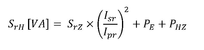
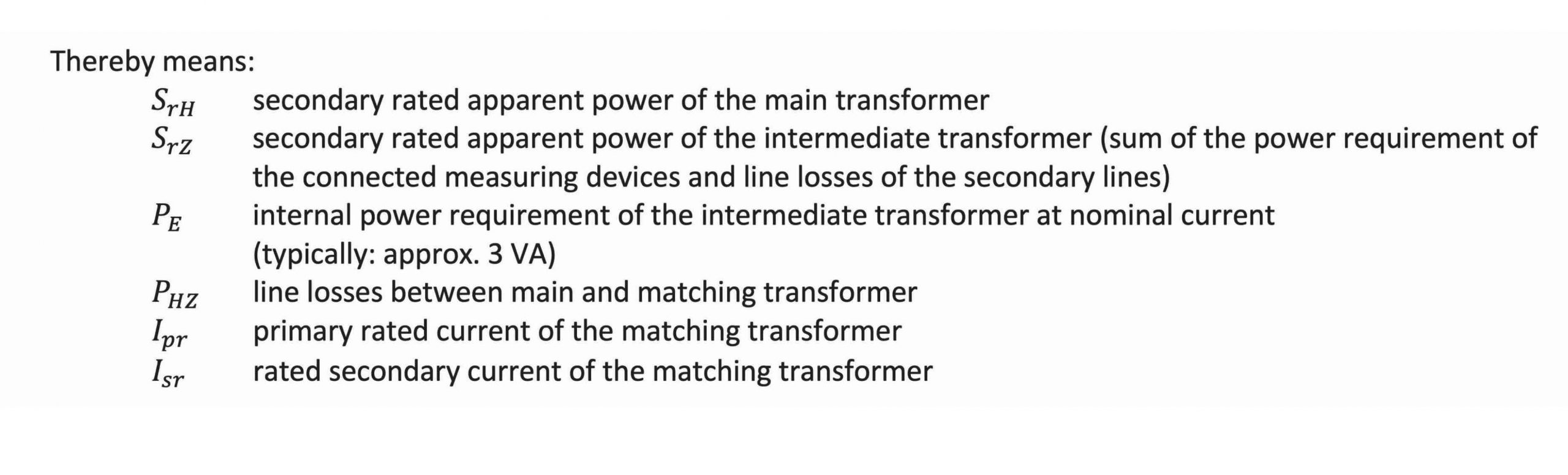
For the correct power rating of the main converter to be used, please use the following formula: