Residual current monitoring-protection

Residual current monitoring in an industrial environment (part 1)
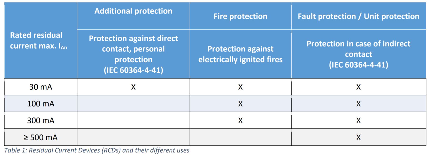
A Residual Current protective Device (RCD) has been a standard component in electrical sub-distribution for many decades. There is also a RCD at home, which has a rated residual current of 30 mA. Tripping between 50 and 100 % of the rated residual current is specified in the international standard. If the 30 mA RCD trips, there must be a residual current of 15 to 30 mA. The threshold of 30 mA is intended to ensure personal protection, which is required wherever freely accessible sockets are available.
In the industrial environment, in addition to the administration buildings, which are protected with 30 mA RCDs, we usually find larger machines that are used for production. Even if these machines do not have any freely accessible sockets, protection using RCDs would also make sense. They are designed to provide safety for three types of protection which are described in the following table.
A system failure can lead to electrically ignited fires. Major damage to the system could possibly also be prevented if a minor defect could be detected at an early stage. A major disadvantage when protecting the systems with an RCD is then an unforeseeable sudden shutdown of the system. In some branches of industry, an uncontrolled and unexpected system shutdown can quickly result in costs in the five to six-figure range.
This is remedied by Residual Current Monitors (RCM) with which the residual current can be measured. An increase in the residual current can be detected and reported at an early stage. A controlled shutdown of the production plant guarantees better coordinated repair measures. The availability of the system can be increased. The probability of a production downtime decreases.
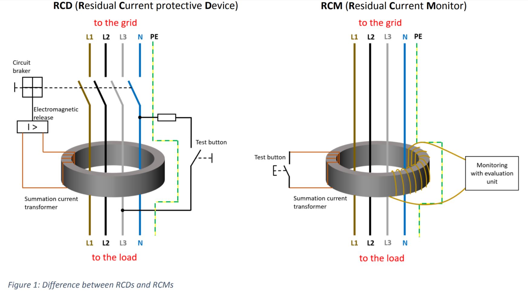
The figure above clearly shows that, in contrast to the RCD, an RCM cannot independently interrupt the supply line. The differential current is only measured and outputted via a suitable interface. In addition, RCMs have one or more relay outputs, which in turn can be used to control circuit breakers.
In addition to availability of the system, safety is also of the utmost importance. Defective systems can not only disrupt production processes, but also lead to personal injury. In Germany the German Social Accident Insurance (DGUV) takes this into account and released the regulation 3, which provides for a regular inspection of the production plant. Part of this so-called repeat test is always the insulation test, which is often very time-consuming and therefore cost-intensive. According to the manufacturer’s information, individual devices in the overall system such as frequency converters or switching power supplies are disconnected for this test, as these can be damaged by the standard insulation test. In addition, the system must be switched off for the measurement of the insulation resistance.
Residual current monitors can also offer significant added value for the company here, because the current international standard IEC 60364-6 (Edition 2.0 – 2016-04) expressly states that measurement of the insulation resistance in the periodic verification can be replaced by a residual current monitoring device in accordance with IEC 62020 which monitors permanently the residual current in conjunction with continuous maintenance by qualified electricians.
A third area of application of the RCM is the protection of production plants against fire. Around 30 percent of all registered fires can be traced back to faults or defects in electrical systems. The protection via a RCD with 300 mA can often lead to false tripping due to the very high system-related residual currents of the system. This is where IEC 60364-4-42:2010+AMD1:2014 comes into play, stating that residual current monitors may be used in conjunction with a circuit breaker to avoid electrically ignited fires due to insulation faults to shut down the system if residual current protective devices (RCDs) are ruled out for technical reasons.
System-related residual currents
As already known from the power quality area, the systems with frequency converter technology represent non-linear loads. There are no sinusoidal currents on the three conductors L1, L2 and L3, but rather a 50 Hz basic oscillation with sometimes large harmonic components depending on the respective semiconductor circuit.
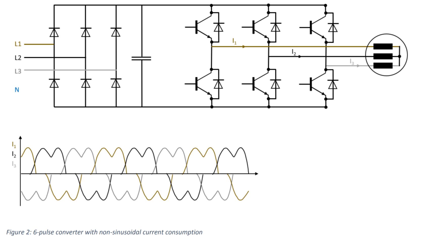
From a power quality point of view, filter measures against high harmonic currents would be desirable in order to minimize negative perturbation on the voltage quality of the supply network. Various filter measures are often carried out by the frequency converter manufacturer in order to lower the THDi . In many cases these passive harmonic filter measures transfer the large harmonic components of the current to the protective conductor (PE). What is very praiseworthy from a power quality point of view becomes an issue for conventional RCDs. A system-related residual current results in a continuously residual current which is detected by the RCD. This system-related residual current already leads to undesired tripping of the RCDs used in many applications, either for personal or fire protection applications.
1 THDi = Total Harmonic Distortion (current), is a measurement of the harmonic distortion present in a signal and is defined as the ratio of the sum of the powers of all harmonic components to the power of the fundamental frequency.
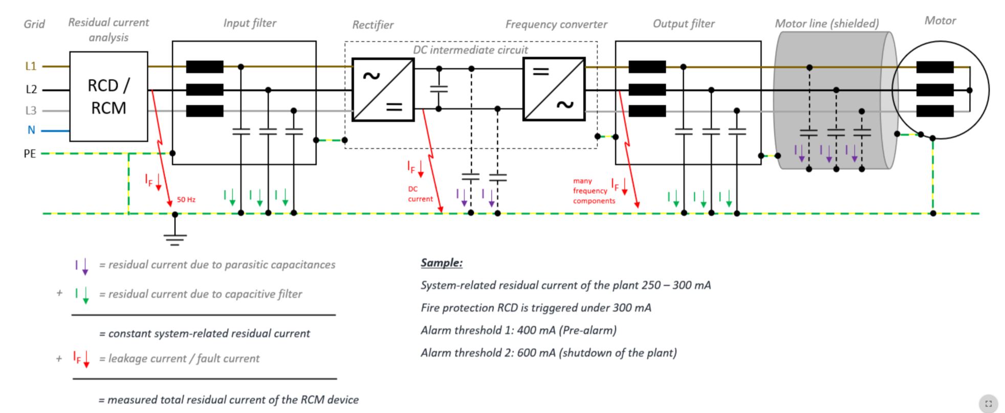
As can be seen in the figure above, residual currents can arise from interference suppression filters or also from parasitic capacitances. The system-related residual current results from these capacitive currents. A leakage current that now occurs due to an insulation fault will increase the base level accordingly. This is then the total residual current that is detected by the RCD or RCM. In some systems, system-related residual currents can trigger RCDs.
Residual currents in practice
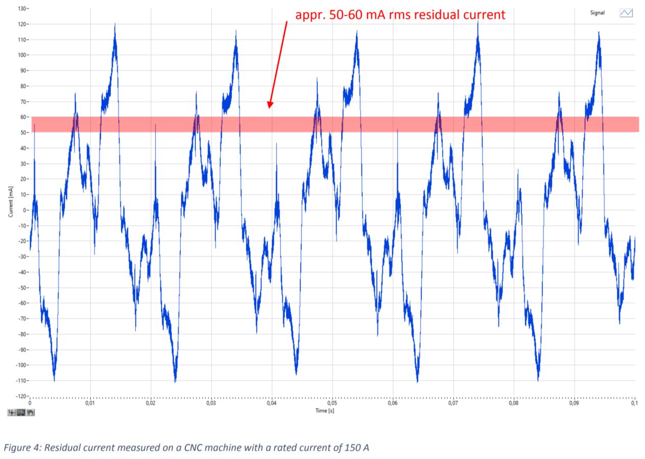
We are now moving from theory to practice and looking at real residual currents on our own production plants. The first system is a CNC machine with a nominal current on the three phases of 150 A. The differential current is approx. 50-60 mA (rms value) and the curve shape looks as follows.
If we break down this signal into its frequency components, the following picture emerges.
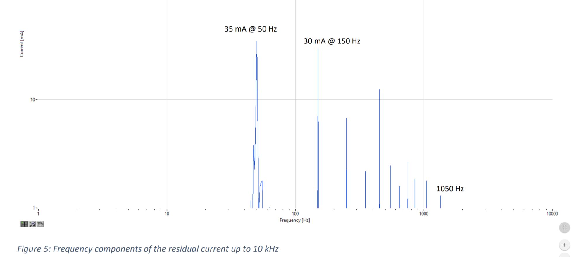
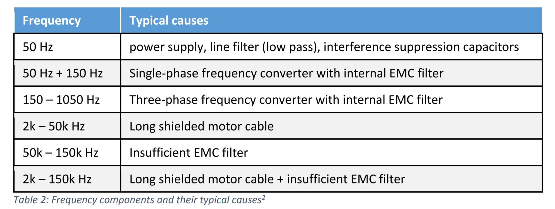
Larger amplitudes are at 50 Hz and between 150 and 1,050 Hz. These amplitudes allow the conclusion that this system is operated with a three-phase frequency converter which is equipped with internal EMC filters. The harmonics are dissipated to earth and thus show up in the system-related leakage current. In general, frequency components can be interpreted according to the following table.
In principle, it would be possible to equip this system with a 300 mA RCD (if the rated primary current of the system is under 125 A, which is the maximum nominal value for RCDs) in terms of system protection. In the German standard DIN VDE 0100-530 (2018-06) , in section 531.3.2 we find the following sentence:
The system-related residual current in protective conductor systems should be a maximum of 0.3 times the rated residual current for residual current circuit breakers in order to avoid undesired shutdowns.
Since a residual current of 50 to 60 mA is measured when the system is in operation, we are below the 90 mA (0.3 × 300 mA = 90 mA) specified in the standard for a RCD for fire protection applications. An uncontrolled switch-off would also be a possible scenario here, because switch-on transients could favour unwanted tripping from 150 mA (50% of 300 mA).
2 Tobias Bozem EPA GmbH
3 DIN VDE 0100-530 VDE 0100-530:2018-06 Errichten von Niederspannungsanlagen Teil 530: Auswahl und Errichtung elektrischer Betriebsmittel – Schalt und Steuergeräte
Let’s take a look at another system where switch-on transients could be detected. This is again a production plant that is equipped with frequency converters.
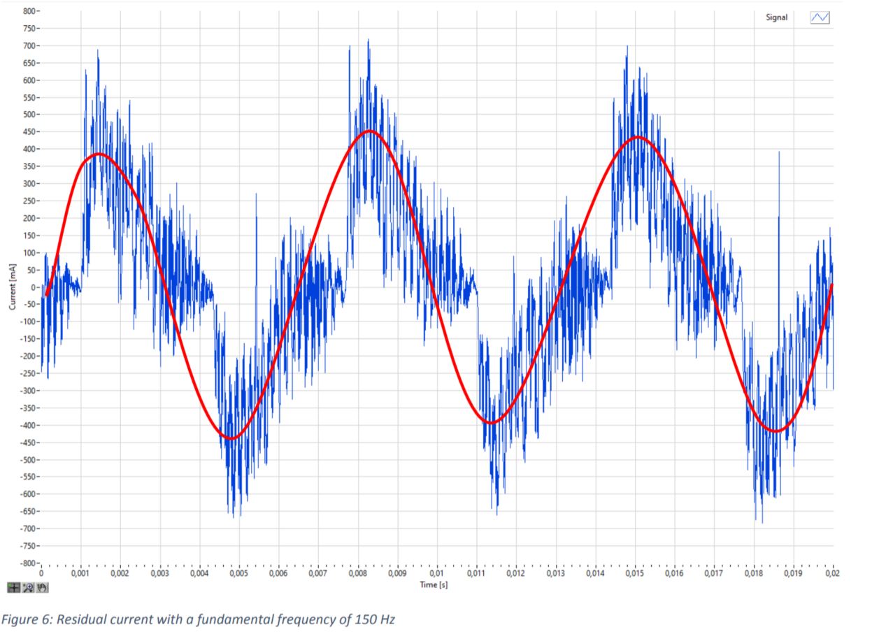
In the time window of 20 ms shown, we can see three almost sinusoidal fundamental oscillations. Three oscillations in 20 ms mean that in a FFT analysis we will see the largest amplitude value at 150 Hz. The higher-frequency components in the diagram show the clock frequency of the frequency converter. It is at 18 kHz and is at least partially diverted either by EMC filters or parasitic capacitances to earth, so that this system-related residual current is also shown in the overall residual current. The effective value of the differential current is between 250 and 260 mA. A 300 mA RCD is not suitable for this system because a possible tripping between 150 mA (50% of 300 mA) and 300 mA is most likely. Here the nominal value of the current as a second criterion is not taken into account.
Now we come to the switch-on transients which are feared in practice and which often lead to false alerts. In the figure below, transients up to 1,800 mA can be seen.
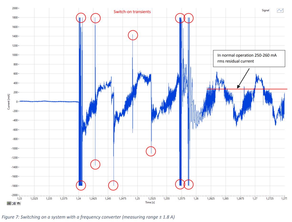
The measurement curves were recorded with the EPA LEAKWATCH measurement system and a measuring current clamp, which covers the two measurement ranges up to 1 and 10 A. With the selection of the 10 A range, the transients might have been even larger. Examples of detected peaks of up to 200 A over 20 µs in the residual current during switching drive controllers on and off can be found in the literature . In addition to false alerts due to switch-on and switch-off transients, residual currents can also have a direct component that can arise in the intermediate circuit of the frequency converter (see Figure 3). This can lead to a changed magnetic operating point in the RCD’s summation current transformer. The residual current flowing through the current transformer can then no longer be transformed to the secondary side in its entire amplitude in the specified transformation ratio. The amplitude of the alternating current component is only partially transmitted or not transmitted at all.
Stationary monitoring of residual currents in practice
Stationary monitoring of residual currents therefore requires a device that can measure AC and DC residual currents. At the same time, options should be available that can suppress false alarms. These central points are implemented in the new RCMB 70 residual current monitor by the MBS AG.
4 G. Schenke, T. Dunz, U. Schüler, M. Schmidt, G. Grünebast: Personenschutz in Netzen mit Frequenzumrichtern, etz Heft S2/2004, VDE-Verlag GmbH, Offenbach
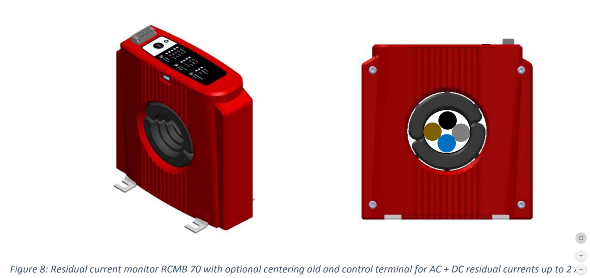
The residual current monitor is based on the zero-flux principle with multiple cores known from the high accuracy current transducers for laboratory applications. AC and DC currents can be detected equally. In addition, it is possible to make various configurations on the control terminal that can suppress the negative effects of the switch-on and switch-off transients on the measurement result.
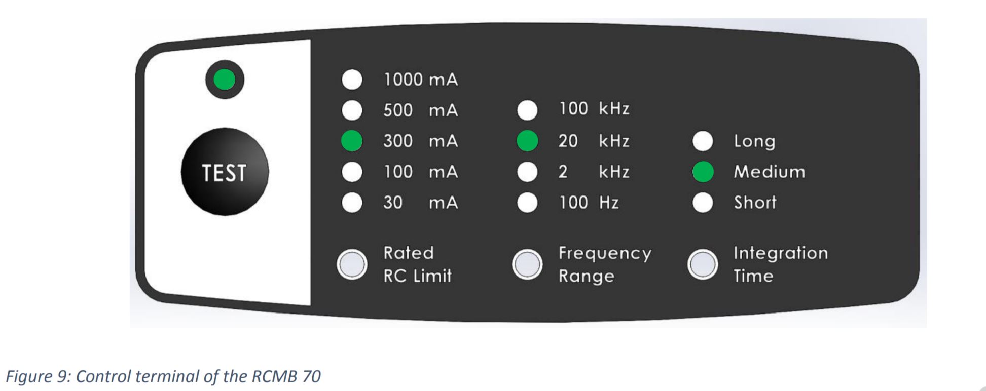
The control terminal allows the user to define different threshold values for the integrated relay (Rated RC Limit). The measured value is output as a true effective value on a 4-20 mA DC interface and can be connected to a wide variety of fieldbus systems or machine controls via appropriate converters. Higher frequency components can optionally be deactivated (frequency range). Short switch-on and switch-off transients can be mitigated by a long integration time window (Integration Time: long = 1000 ms) as a mean value over the integration interval. The maximum switch-off time of 5 s valid for machines can still be clearly undercut with this configuration. At the same time, the measuring system is highly accurate, if the relevant cables are centralized and bundled in the round window of the sensor, even with small residual currents.
5 DIN EN 60204-1 VDE 0113-1:2019-06 Sicherheit von Maschinen – Elektrische Ausrüstung von Maschinen
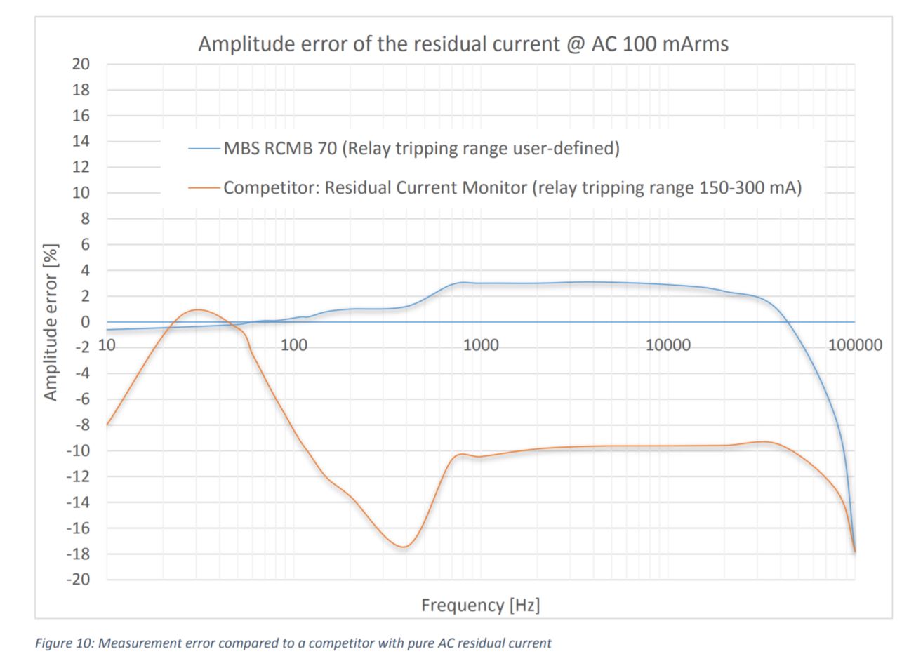
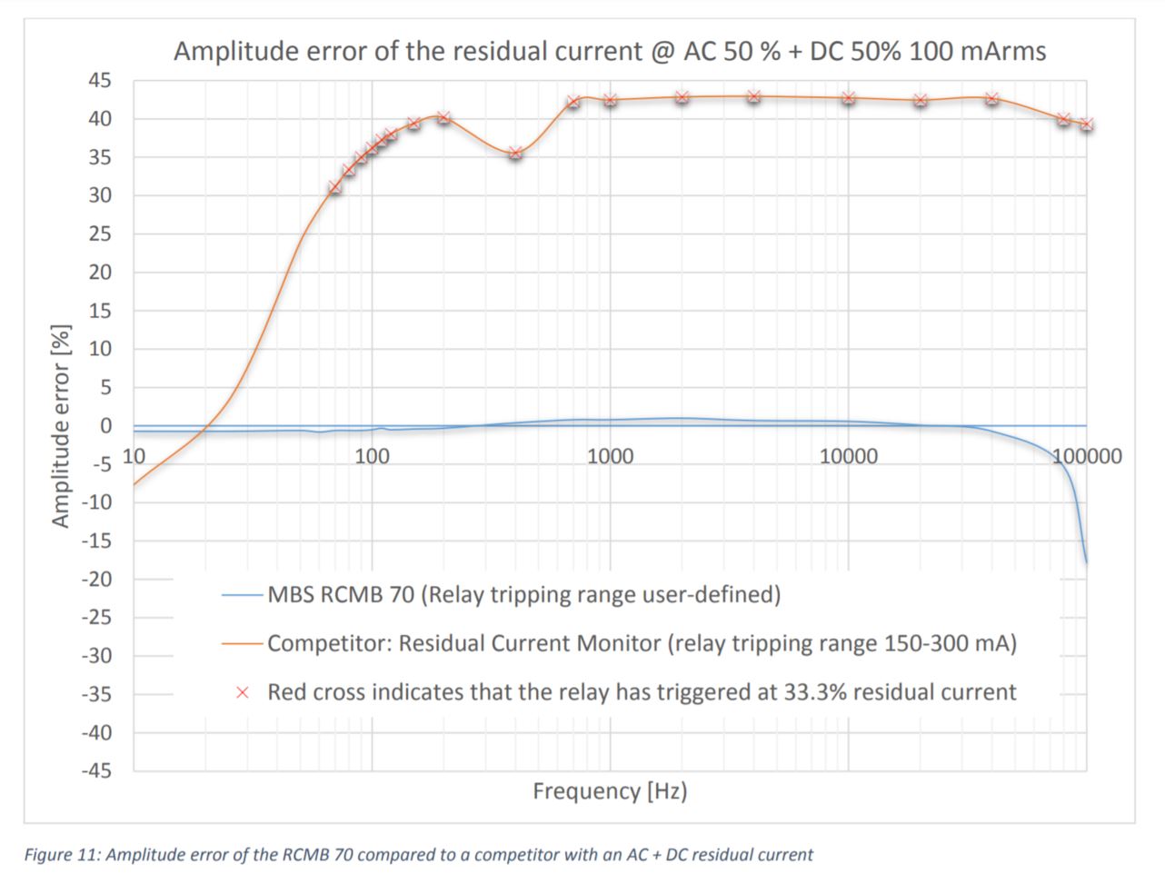
If a residual current represents now a sum of AC and DC components, which can certainly happen in systems with frequency converters, the differences are even clearer.
Now nothing should stand in the way of machine monitoring.