Power quality measurements in all EVU voltage levels up to 150 kHz – Is that possible?
A reliable energy supply has become an important location factor for many companies.
While grid failures and voltage fluctuations were among the most important parameters of supply quality in the past, voltage transients and voltage transients or voltage harmonics are becoming increasingly important.
This is primarily due to the ever-increasing number of non-linear consumers and many decentralised renewable energy sources.
decentralised renewable energy sources. In order to ensure uniform standards for the supply of electrical energy in Europe
the minimum requirements for power quality are defined in a European standard. This is EN
50160, which is entitled “Voltage characteristics in public electricity supply networks”. This standard is to be understood as a
standard for electrical energy and is therefore also used as the applicable product standard in electricity supply contracts.
product standard in electricity supply contracts. In February 2014, the Federal Court of Justice made it unmistakably clear that electricity is also subject to the Product Liability Act. is also subject to the Product Liability Act. This means that the distribution system operator is liable for damage to electrical consumers that attributable to inadequate voltage quality on the part of the distribution system operator.1 For this reason, many meter manufacturers now offer measuring devices that prepare automated quality reports in accordance with EN 50160. Also digital meters are also increasingly offering power quality functions in accordance with EN 50160.
While the measuring devices in the low voltage can process the voltage directly, we are dependent on voltage transformers or voltage sensors for medium and high voltage. The voltage quality is usually measured on older systems. However, the installed voltage transformers usually do not indicate the transmission behaviour at higher frequencies on the rating plate. The devices are only specified for the 50 Hz fundamental frequency of the mains. Measurements in accordance with EN 50160
require a frequency range up to 2 kHz. We want to investigate the question of whether the existing devices are suitable for measurements up to 2 kHz are suitable.
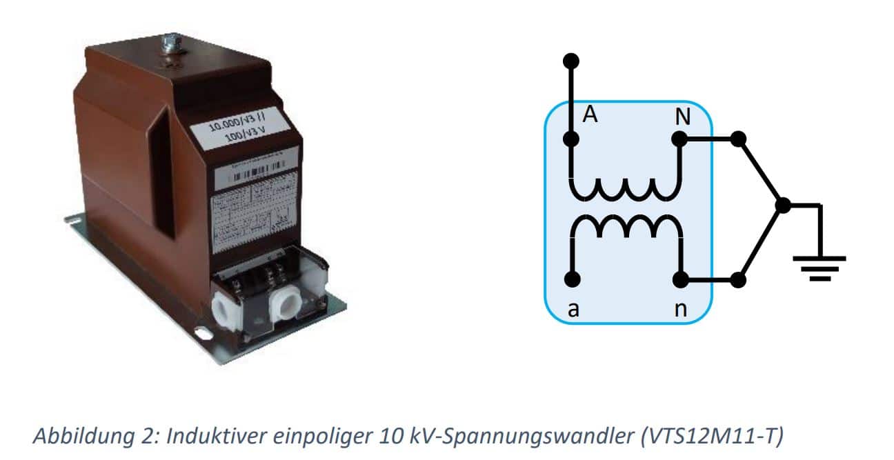
Almost all of the voltage transformers used are inductive transformers that operate according to the transformer principle.
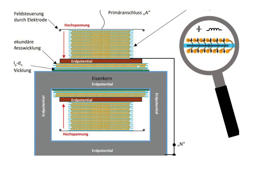
Figure 1: Model of the active part of a MV voltage transformer
In detail, the primary coil not only consists of inductive copper windings, but also has capacitance due to the individual insulated layers.
by the individual layers insulated from each other. The capacitances between the individual windings also contribute to the total capacitance of the primary coil. This results in a resonant circuit consisting of inductance, capacitance and ohmic resistance,
which must also have a corresponding resonant frequency.
In order to find this resonant frequency, a standard 10 kV voltage transformer is now measured using the “frequency sweep method”
with 6,400 measuring points up to 10 kHz. The measurement setup is based on the recommendations of the technical report IEC
TR 61869-103.
We have found what we were looking for!
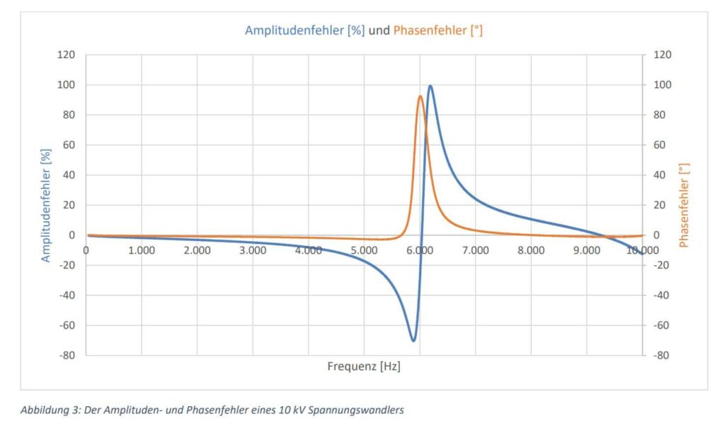
A resonance point can be recognised at approx. 6 kHz. While the transducer transmits the primary signal acceptably up to approx. 5 kHz at approx, at 6 kHz there is an amplitude error of approx. 100 % and a phase error of 90 °. A reliable PQ analysis up to e.g. 9 kHz
cannot therefore be carried out with this voltage transformer.
Despite the standardised regulated voltage levels, every transformer manufacturer has a large number of different transformers
with different primary coils in order to be able to fulfil the customer’s various secondary configurations.
These transformers have already been delivered and installed in measuring fields. The manufacturer can only provide a rough estimate of the
The manufacturer can only carry out a rough calculation of the first resonance point in conjunction with the archived production documents. However, the resonance point measured in practice
resonance point measured in practice can deviate from the calculation result by several kHz. It is therefore very difficult for transducer manufacturers
difficult to make reliable statements for devices that have already been delivered.
A contribution from the technical-scientific organisation CIGRE / CIRED offers metering point operators good assistance.
A guideline for power quality measurements has been published here, which provides a meaningful table regarding the frequency transmission behaviour of voltage transformers provides a meaningful table.
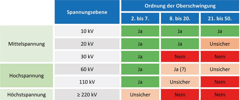
Tabelle 1: CIGRE / CIRED Richtlinien für Power Quality Messungen WG C4.112 TECHNICAL BROCHURE 596
It can be seen that 10 kV voltage transformers can generally be used for PQ measurements up to the 50th harmonic (2.5 kHz).
This statement is consistent with our measurement results in Figure 3.
However, according to the table, devices have already been found in the 20 kV range that do not provide reliable measured values on the secondary side from the 21st harmonic onwards.
measured values on the secondary side. In the 30 kV range, a blanket approval has even been given only up to the 7th harmonic.
harmonics. We state that only 10 kV voltage transformers in existing systems can be used for reliable EN 50160 measurements.
existing systems can be used for reliable EN 50160 measurements. At voltage levels 20 and 30 kV, information must be provided by the transformer manufacturer.
The transformers analysed here are exclusively single-pole devices. Two-pole voltage transformers, which can still be found in
older existing systems cannot be used for analysing harmonics.
This is due to the voltage measurement between the conductors.
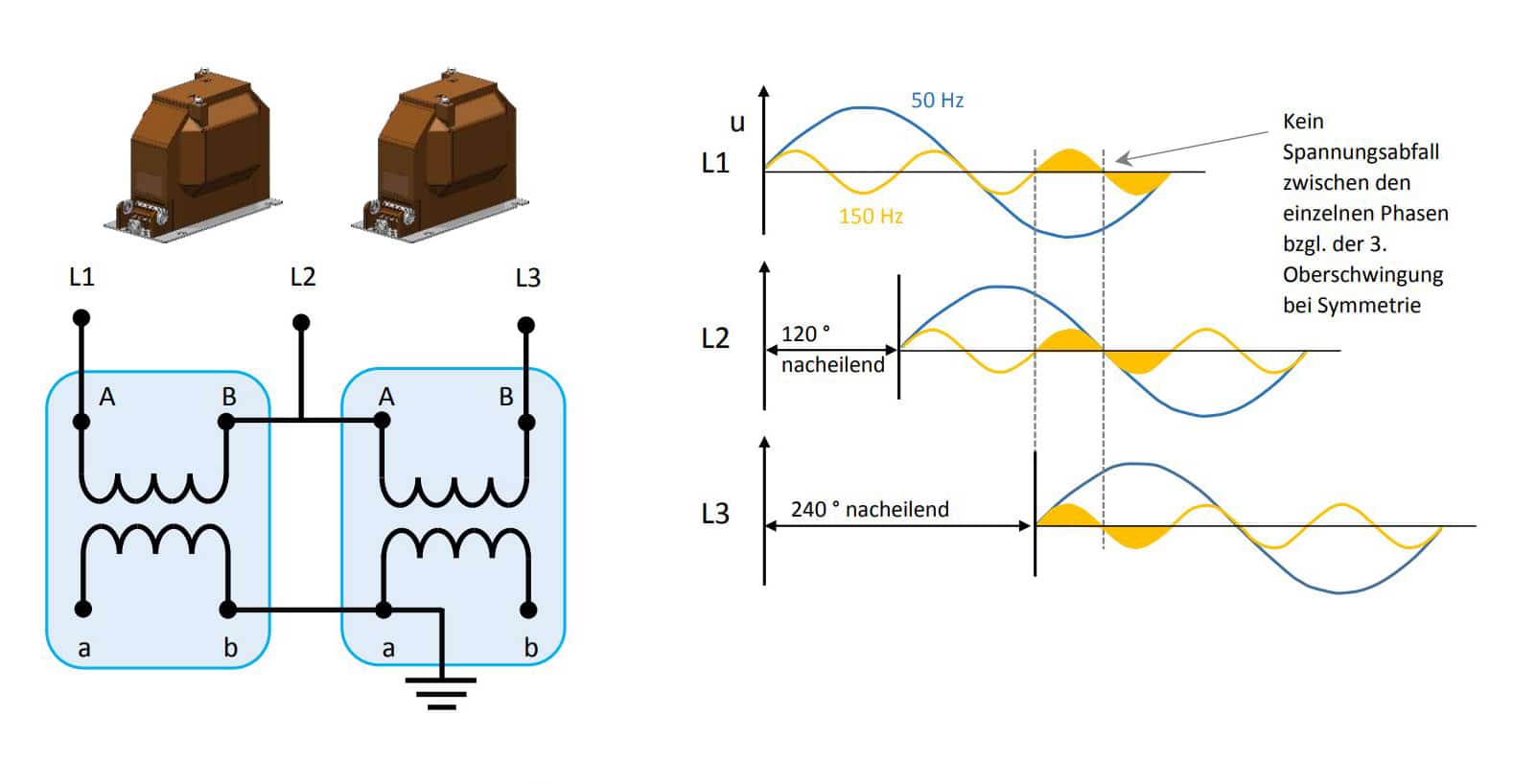
Despite the 120 ° phase offset of the 50 Hz conductor voltages, the amplitude values of the superimposed 3rd harmonic
are not offset and therefore cannot generate a voltage difference between the conductors. This generally applies to all harmonics divisible by 3
divisible harmonics. The THDu obtained by the V circuit is therefore reduced by the values of the voltage harmonics that can be divided by three (3, 6, 9,…).
The question also arises as to whether measurements up to 2 kHz are still sufficient. In the current DIN EN 61000-2-2
(Environmental conditions – Compatibility levels for low-frequency conducted disturbances and signal transmission in public low-voltage
public low-voltage networks) already specifies limit values for voltage up to 150 kHz.
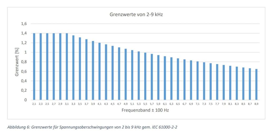
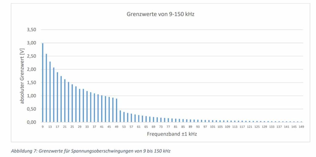
The EN 50160 standard cited in the electricity supply contracts was updated in 2020, but limit values beyond 2 kHz have not yet been bindingly defined.
have not yet been defined as binding. A voltage measurement up to 2 kHz is therefore sufficient for determining the quality of the
electrical energy is sufficient. However, PQ measurements up to 9 kHz are already required for the grid connection of feed-in systems.
MBS AG therefore offers frequency-optimised voltage transformers up to 24 kV for the measuring range up to 9 kHz. The
accuracy requirement for these transformers is defined in IEC 61869-6. The amplitude and phase errors are as follows
as follows.
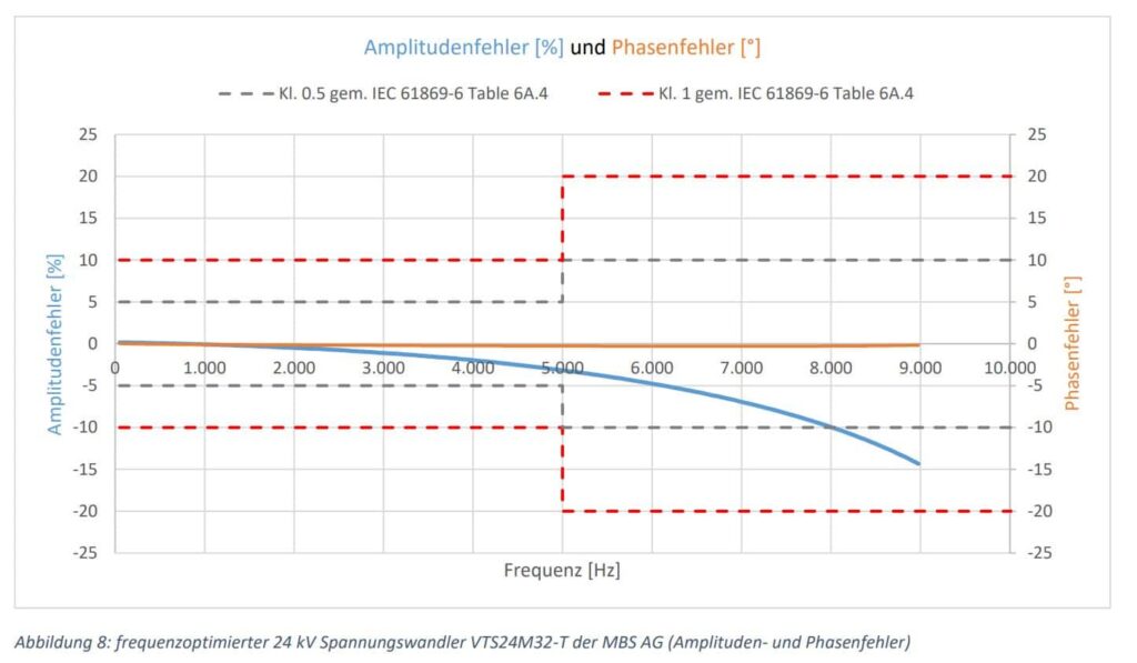
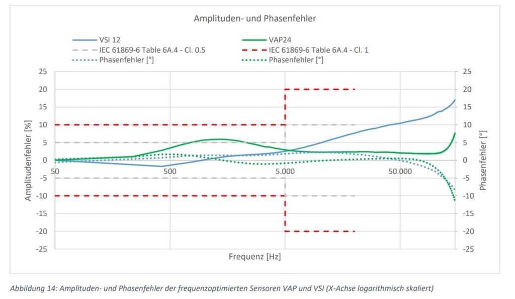
The transducer maintains class 0.5 up to approx. 8 kHz and class 1 from 8 kHz onwards. These voltage transformers therefore enable
reliable PQ measurement up to 9 kHz and, like all other medium-voltage transformers from MBS AG, are also SF6-
free.
Many experts are already assuming that PQ measurements of up to 150 kHz will also be carried out in medium voltage in the future.
will also take place in medium voltage. Some of the current mobile PQ analysers already measure up to at least 150 kHz, which may well be necessary for a comprehensive fault analysis.
This may well be necessary for comprehensive interference analysis.
The range up to 150 kHz cannot be technically realised with inductive voltage transformers. The first resonance point of 24
kV devices can only be shifted into the range from 10 to 20 kHz. Voltage sensors based on the voltage divider principle offer an alternative.
principle of the voltage divider. As a reminder, the basic principle is shown here once again.
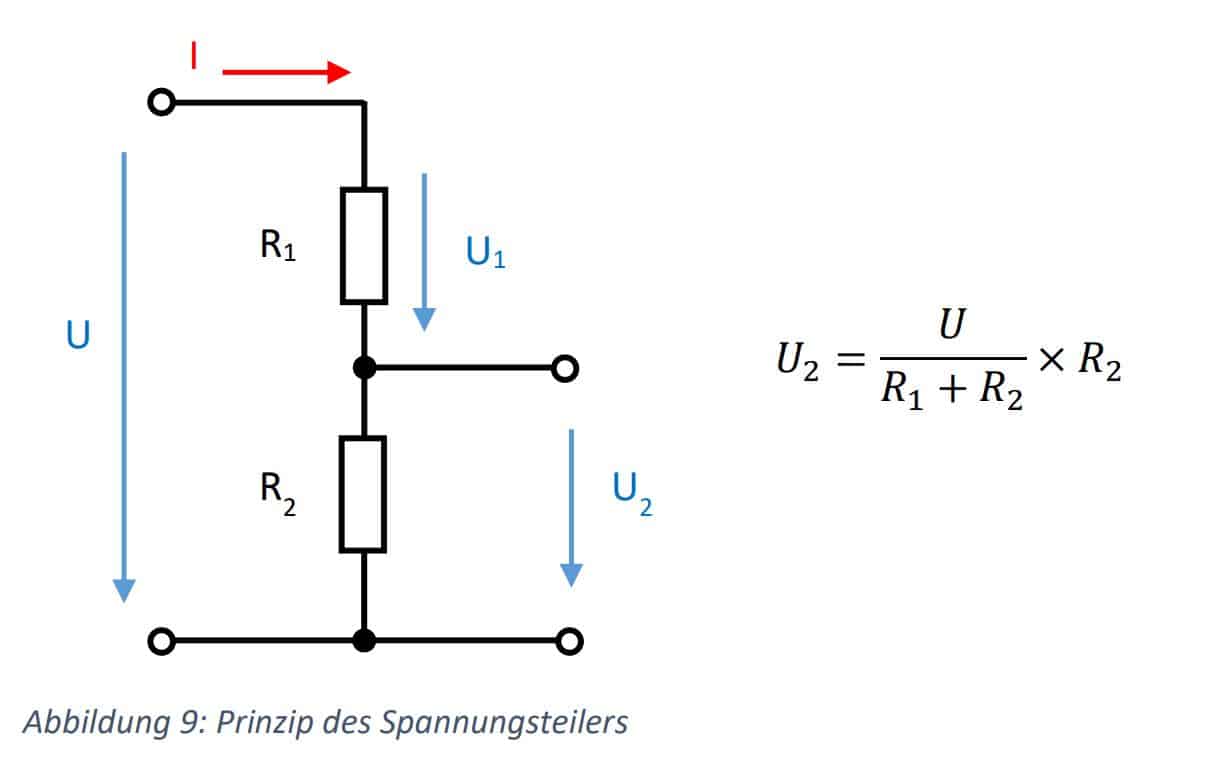
Already today, voltage sensors are mainly installed in existing local grid stations that require additional voltage measurement on the medium-voltage side.
voltage measurement on the medium-voltage side. Measuring fields with conventional inductive voltage transformers
can only be retrofitted in rare cases for space reasons. A proven method is to mount sensors in so-called
so-called T-connectors. This solution saves space and installation is carried out by trained personnel in a
a reasonable time frame. While the cone of the symmetrical connector is standardised in accordance with IEC 50181, the cone of the compact
compact T-connector has slightly different dimensions depending on the manufacturer. The voltage sensor intended for the compact T-connector
VAPxx-S voltage sensor intended for the compact T-connector can, however, be used in the slightly different T-connectors of all well-known
manufacturers without having to worry about partial discharges. For the new compact T-connector
from Nexans (480 TB), there is already a suitable sensor with the VCPxx-S.
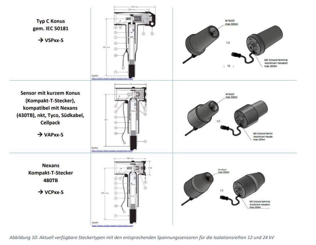
The sensors shown in Figure 10 can be used up to a maximum of 24 kV. A 36 kV variant is already planned.
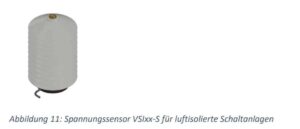
MBS AG has a sensor for air-insulated switchgear or measuring panels that is already being used in new installations and retrofits.
used in both new installations and retrofits.
While the accuracy class at 50 Hz is noted on every rating plate of the sensors and is therefore the responsibility of the manufacturer
manufacturer, the manufacturer often does not provide any protocols or reliable statements for measurements beyond 50 Hz.
provided by the manufacturer. In the market, end users often have the preconception that resistive dividers transmit harmonics very well.
can generally transmit harmonics very well. This will be analysed below.
An ohmic divider basically consists of two almost ohmic resistors, but these resistors always have
parasitic inductive and capacitive components. A capacitance is also formed around the high-voltage resistor, so that in the technical literature does not speak of ohmic dividers, but of ohmic-capacitive dividers.
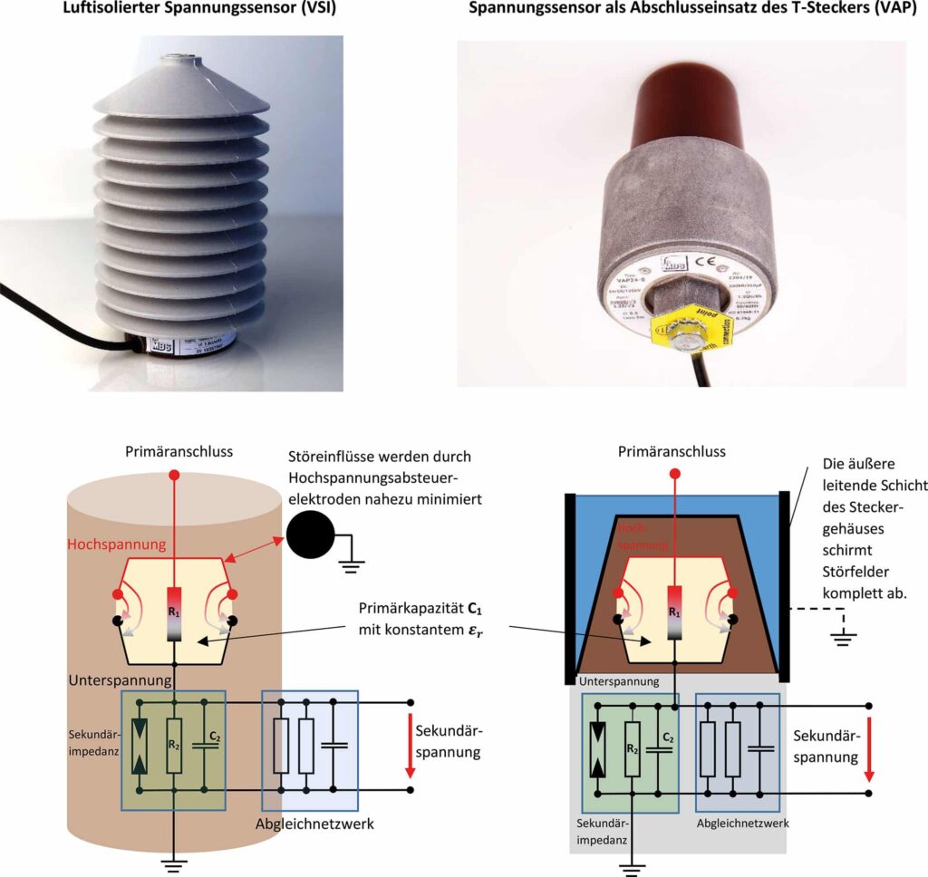
Abbildung 12: Prinzipschaltbilder eines luftisolierten Spannungssensors (VSIxx-S) und eines Spannungssensors als Abschlusseinsatz des T-Steckers (VAPxx-S)
As can be seen in the schematic diagrams, the primary capacitance must also be equalised on the secondary side. In order to
sensors, a calibration network is also required in the sensor, through which a fine calibration can be carried out after encapsulation.
fine adjustment can be carried out after encapsulation. However, this consists exclusively of passive electronic components.
The question now arises as to whether ohmic-capacitive sensors in the medium voltage range can be used for PQ measurements without further ado.
can be used for PQ measurements. The following figure shows a competitor’s 50 Hz sensor and MBS’s own 50 Hz sensor from 50 to 150 kHz
have been measured with regard to amplitude and phase errors.
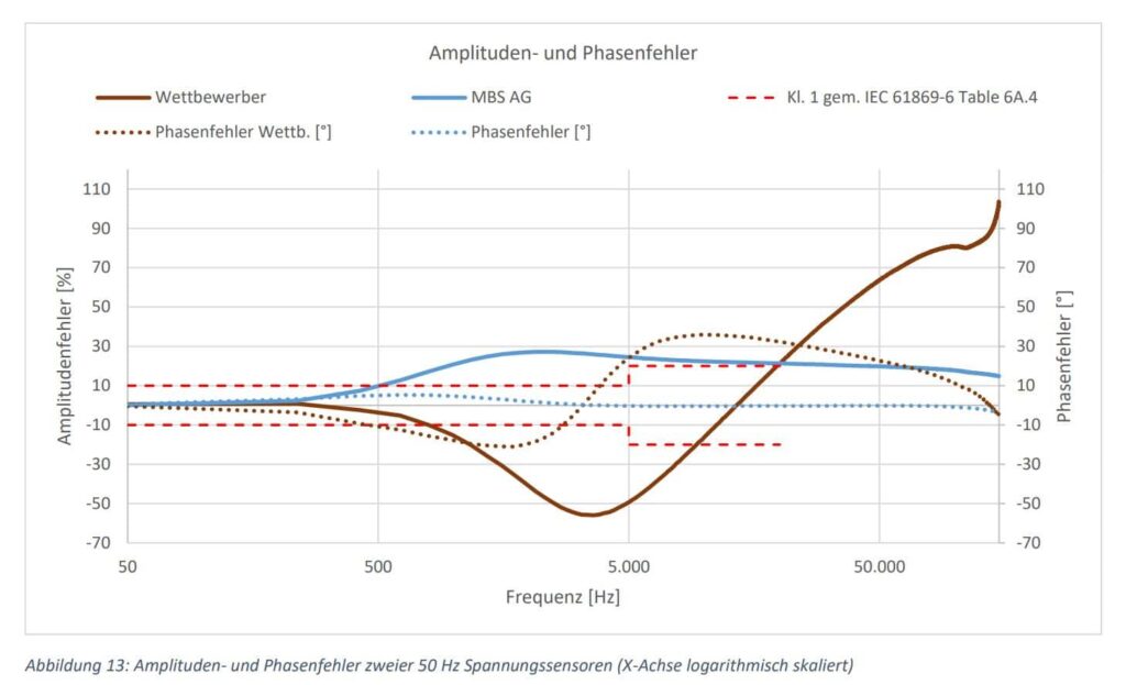
Both sensors violate the minimum requirements of class 1 for PQ measurements in accordance with IEC 61869-6.
transmission behaviour, the adjustment network must also be optimised for higher frequencies.
Frequency-optimised sensors are therefore essential for PQ measurements in order to meet the minimum requirement (Class 1 according to IEC
61869-6) to be met. Transmission curves from current customer projects are shown in the following figure.
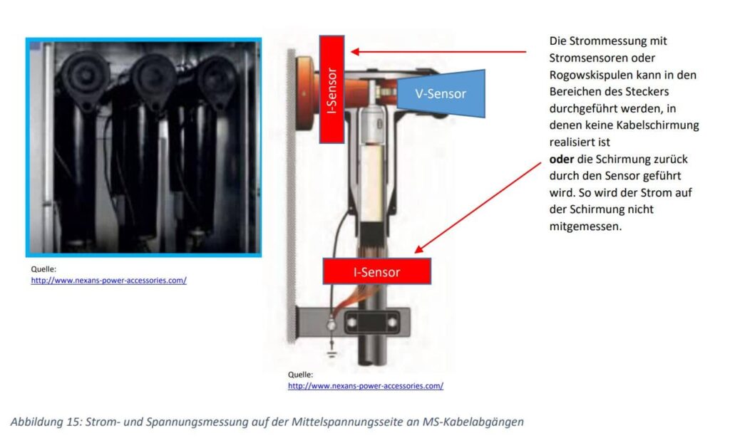
The voltage sensors are usually installed with corresponding current sensors. Unlike conventional current
current transformers, a voltage signal is output on the secondary side. However, broadband Rogowski coils can also be used.
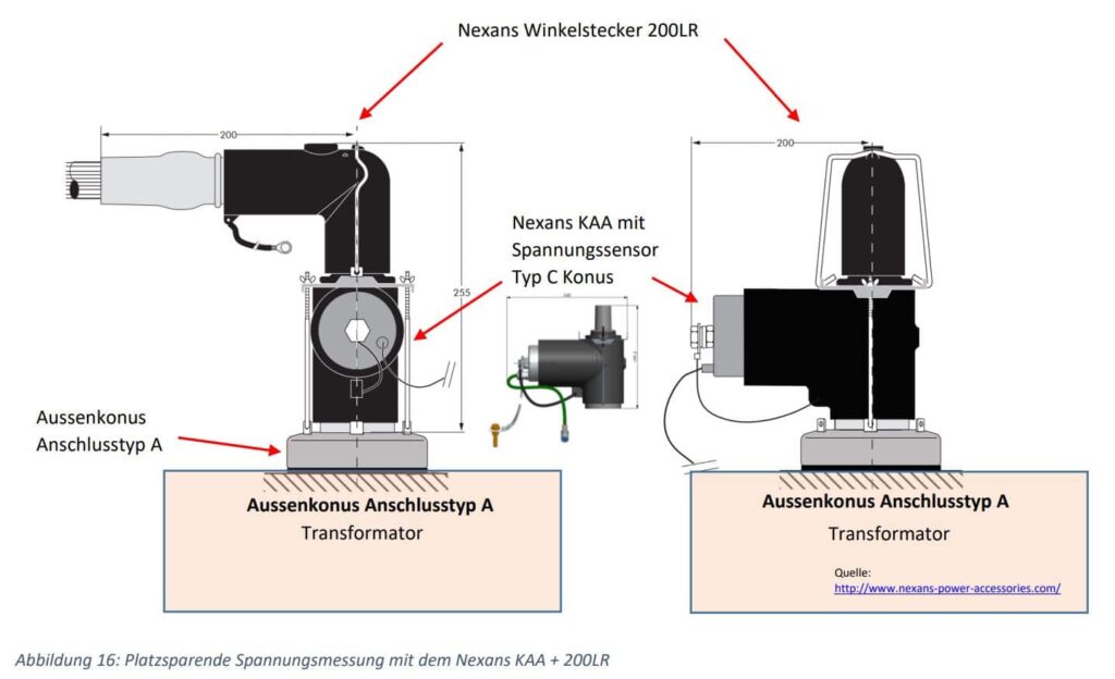
Various cable connector manufacturers also offer adapters for external cone A. This allows voltage measurements
can be realised directly on the transformers to save space.
When selecting the measuring device, please note that the voltage sensors mentioned here can provide a maximum of 10/√3 volts on the secondary side.
can provide a maximum of 10/√3 volts. In Germany, the standard 3.25/√3 V has already been established. For current sensors
225 or 333 mV are generally used.
This often poses a problem for the energy supply company when purchasing a mobile power quality analyser. In contrast
In contrast to the traditional inductive voltage transformers with 100/√3 V, the voltage sensors only provide a small signal
up to a maximum of 10/√3 V. In the low-voltage range, the voltage signals are tapped directly from the live conductors.
tapped directly. Frequency-optimised high-voltage transformers, which are designed as RC dividers, generally provide 100/√3 V like conventional voltage transformers.
provide 100/√3 V like conventional voltage transformers. This results in a wide range of secondary voltages in the environment of a
EVU.
Translated with www.DeepL.com/Translator (free version)

Um eine ausreichende Auflösung und Genauigkeit garantieren zu können, sollte ein mobiles PQ-Messgerät auf diese
unterschiedlichen Messspannungen ausgelegt sein.
Das derzeit einzige mobile Messgerät, das diesen Anforderungen gerecht wird, ist das PQA 8000H-P der Firma NEO MESSTECHNIK.
Hier gibt es umschaltbare Spannungseingänge für 600 Vpeak und 10 bzw. 20 Vpeak. Mit dieser Option ist es dem EVU möglich, in
den verschiedenen Spannungsebenen hochwertige PQ-Messungen vornehmen zu können.
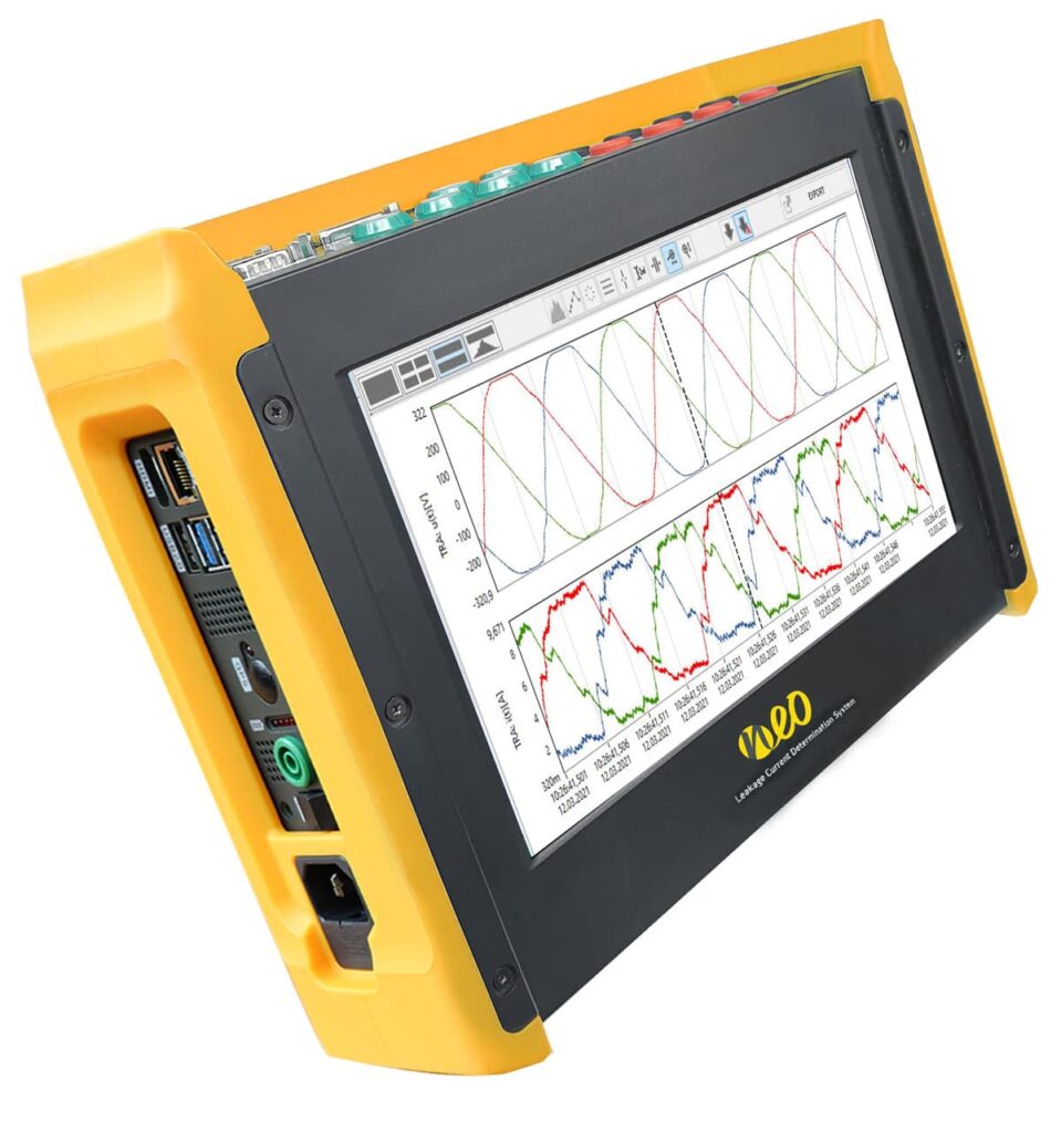
▪ FFT analysis up to 500 kHz (voltage & current) in 2 kHz bands
(according to the international standard IEC61000-4-30)
Scope view with 1 MS/s
▪ 4x voltage measurement / up to 8x current measurement
▪ Display and recording of the digital PLC data stream
▪ Two voltage measurement ranges (switchable) of 600 Vp and 10 Vp
▪ All voltage inputs separate (CAT III 1000 V / CAT IV 600 V)
▪ Direct supply of current sensors from the device
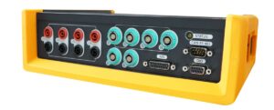
Abbildung 17: Mobiles PQ-Messgerät PQA8000H-P mit umschaltbaren Spannungseingängen speziell für EVUs
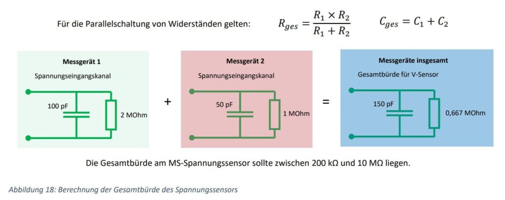
The input impedance of the voltage channels is 10 MOhm || 2 pF. Conventional voltage transformers in the medium voltage range are specified in terms of class accuracy with a load power in VA. Values between 5 and 20 VA are common. The class stated on the rating plate applies to 25 to 100 % of this power. The power requirement of the mobile PQ device is negligible at the usual secondary output voltage of 100/√3 V.

The measuring device can therefore be operated in parallel with the connected measuring devices without affecting the accuracy.
The situation is different for medium and high voltage sensors. Here, the RC dividers are precisely
load resistance. An extra terminal for the PQ measuring device is therefore often installed in the high voltage.
In medium voltage, the sensor must be precisely matched to the measuring device. However, measuring devices can also be operated in parallel here. By using additional resistors in parallel, the PQ measuring device can be simulated when not in use.
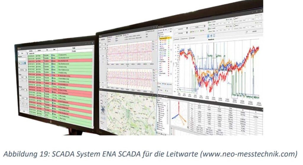
When using several measuring devices in different measuring stations, a convenient connection to the ENA SCADA
system is possible.
It can be stated that by using ohmic-capacitive voltage sensors in the medium voltage in conjunction with a switchable mobile PQ analyser, measurements up to 150 kHz can also be carried out.
in conjunction with a switchable mobile PQ analyser, measurements up to 150 kHz can also be carried out. With
RC dividers in the high voltage can currently cover a measuring range of up to 30 kHz. Adoption of the limit values
from the current IEC 61000-2-2 into EN 50160 for low and medium voltage.
Autoren:
Roland Bürger (MBS AG)
Business Development/Entwicklung, MBS AG, Sulzbach-Laufen
rbuerger@mbs-ag.com
Bernhard Grasel (NEO MESSTECHNIK)
Sales Manager, NEO Messtechnik, Zöbern Österreich
bernhard.grasel@neo-messtechnik.com
