
Billing measurements of electrical energy in Germany
A complicated issue
For billing measurement of electrical energy in Germany, at higher currents and voltages that are no longer controlled by the energy meter, inductive current and voltage transformers are used without exception. These devices are subject to the transformer principle. While current transformers represent a transformer almost in short-circuit operation, voltage transformers are transformers that are connected with high impedances in the secondary terminal (idle operation). If these devices are to be used for billing measurements in Germany, the instrument transformer manufacturer needs a type test certificate from the Physikalisch-Technische Bundesanstalt (PTB). After the production and testing of the instrument transformer, the manufacturer certified by the PTB can provide the approved products with a declaration of conformity. Despite this evidence, problems arise in practice in the interaction with electronic measuring devices like billing meters.
Current transformer
To operate the current transformer correctly, some background knowledge is required. IEC 61869-1 and -2 are currently valid for current transformers. The following accuracy classes for measurement purposes are listed here:
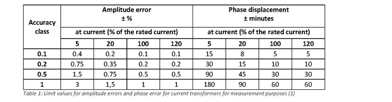
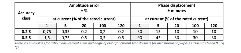
The designation of the accuracy class indicates the percentage amplitude error of the current transformer at the primary rated current. Current transformers for billing measurements require at least class 0.5. Since a larger amplitude error is tolerated with a smaller current than the rated current, an even narrower error window is often required at billing points in which the current transformer is rarely operated during nominal operation. The standard offers classes 0.2 S and 0.5 S. In contrast to the normal measuring classes, the first accuracy value is defined at one instead of five percent of the rated current. The permitted error values for lower amplitudes are also defined significantly smaller.
When selecting the rated power, the measuring point operator is bound to the rated power standardized by the PTB. (1)

According to the applicable standardization, as well as in accordance with the PTB test rules, billing current transformers must comply with the accuracy requirements placed on them with an external burden between 25% … 100% of their rated burden on the rating plate. However, the value 1 VA was set as the smallest test burden for billing current transformers. It should also be noted that the power factor for all measuring points is 1.0 below 5 VA. All powers from 5 VA and above are measured with a power factor of 0.8. Only these measuring points must be in the class specified on the rating plate. If a 10 VA class 0.5 current transformer is now burdened with only 0.5 VA, this means that this measuring point does not have to be located in the specified accuracy class.
A larger and therefore impermissible error value for the overall measuring system would be possible. This scenario is ubiquitous in Germany, since the digital measuring devices hardly need any power anymore. Common medium voltage meters only load the current transformer with approx. 2 to 100 mVA. Even with the smallest permissible design burden of 1 VA, these values would not be checked. This leads us to the question of how the current transformer behaves in the event of an underutilization.
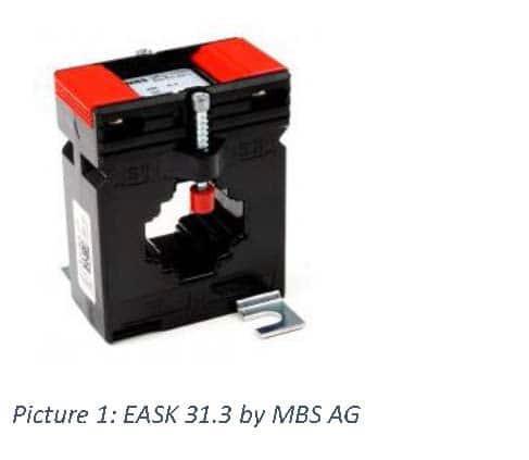
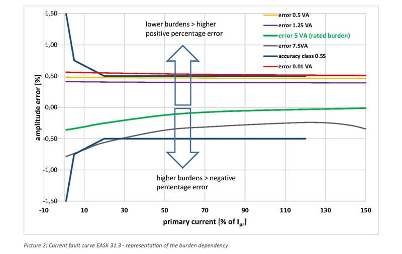
The error curves of the EASK 31.3 current transformer are plotted in the figure above. The current transformer is specified with 5 VA in class 0.5 S. If the converter is now burdened with not unusual 0.010 VA, the error curve in the positive amplitude error range “slips” slightly out of class. The error is between 0.5 and 0.6 percent. Accordingly, between 0.5 and 0.6 percent more electricity is included in the power calculation of the meter than actually flows in the copper busbar. However, if the ct is overloaded with 7.5 VA, the error curve is below the 5 VA error curve in the negative percentage error range. Here, between 0.2 and 0.5 percent less electricity is included in the power calculation.
To get a feeling for the monetary impact, the following assumptions are made:
- 600 Arms primary rated current on the copper busba
- 230 Vrms between electrical cundoctor and-earth
- Operating time: 8,760 hours per year
- Energy price: 0.2 EUR per kWh
Under these boundary conditions, a shift of 0.1 percentage points (e.g. 0.3 percent instead of 0.2 percent amplitude error) bills 1,214 kWh per phase more per year. With an assumed price of EUR 0.2 per kWh, the result is EUR 728 per year in the three-phase system. In 20 years it will be 14,566 EUR. With a general error of 0.4%, the result will be EUR 58,263 in 20 years.
We come now from the low voltage level to the medium voltage level. The effects here are even more dramatic, since the voltage in most cases in Germany is 20,000 / √3 volts between conductor and earth. Here, the shift of 0.1 percentage points for the current transformer signal with the same boundary conditions leads to EUR 36,415 annually in the three phases. After 20 years, the costs already add up to EUR 728,293.
Voltage transformer
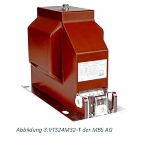
Like current transformers, the voltage transformers required in medium voltage must also meet the accuracy classes defined in IEC 61869-1 / -3. There are also standard burdens specified by the PTB in Germany.
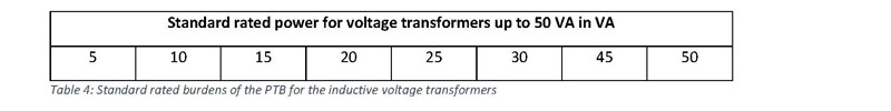
As with current transformers, the lower measuring point is 25 percent of the rated burden. Values below the 25 percent do not have to be within the defined class limits. Here too, it is not improbable that the current digital energy meters with an external energy supply only load the voltage converter up to a maximum of 100 mVA. Accordingly, the statutory minimum burden of 1.25 VA (25% of 5 VA rated burden) is nowhere near achieved.
Although the current standard for inductive voltage transformers (IEC 61869-1 / -3) already has a newly defined burden range I that takes into account the relative high input impedances of the energy meters and the associated low rated power at the secondary output of the voltage converters, only for voltage transformers with declaration of conformity the burden area II is taken into account. In addition to the lower 25 percent measuring point, this defines a power factor of 0.8. The load range I intended for high-resistance measuring devices defines the practical power factor at 1.0 and the lower measurement point at 0 VA, but this new load range is not permitted for voltage transformers which have to fulfill the PTB rules. As a result, the voltage transformer are likely to be underburdened in practice. In addition to the problem of small burdens in practice, there is another issue that needs to be considered.
In addition to the external supply of the digital meter, the meter can be supplied with the necessary energy via the voltage path. This creates further problems. This is because the energy meters are usually operated with different communication interfaces, especially in the medium voltage range. Here, outputs of up to 10 VA can be called up by the voltage transformer. This is probably the reason why the new TAR (new medium voltage standard for utilities in Germany) specifies voltage transformers with 15 VA in class 0.5. However, the communication units such as GPRS or LTE radio modules only send the data to the corresponding server in certain time windows. The power requirement of the counting device can therefore be described as fluctuating strongly. Typical values are between 1 and 10 VA. As can be seen in Figure 3, the modem module now ensures that the complete error range of the voltage converter is traversed from approx. +0.65 to -0.15% ratio error. We note that the operating state of the modem significantly influences the burden on the voltage transformer. The billed energy is thus significantly influenced.
This leads to crazy connections. For example, prolonged heavy rain that affects the radio connection of the LTE modem means that the energy supplier receives less money for the same electrical energy. The reason for this is that the LTE modem may not be able to establish a connection if the radio connection is poor. As with a cell phone, dial-up attempts are made again and again. The LTE modem requires energy for this and thus loads the voltage converter with the defined maximum burden of maybe 10 VA. As described above, there is an amplitude error of the voltage converter at 10 VA load of approximately -0.15% at peak load. On the other hand, if the LTE modem is in standby mode, an amplitude error of approx. 0.65% can be expected.
In order to better understand the different load scenarios, Figure 3 shows a typical fault diagram of a voltage converter. The analyzed device has a measuring winding and is specified with 15 VA in class 0.5.
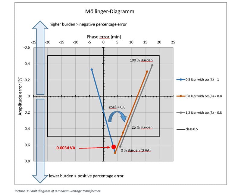
A design was deliberately chosen in which only the 25 percent measuring point and the 100 percent measuring point of the 15 VA are in class 0.5. The blue line shows the error rate from 0 to 15 VA with a power factor of 1. The amplitude error is -0.33 percent at the nominal rated power of 15 VA. However, since the area of burden II applies to billing voltage transformers, the fault line is turned to the power factor 0.8. Furthermore, the measurement classes are defined for a voltage converter of 80 to 120 percent of the nominal voltage. The two error lines in orange and gray are relevant. It can be seen that the converter in idle (0% burden) in the positive percentage error range is not in the class. If we now take a measuring device with a non-unusual input impedance of one megaohm, for example, this results in a power of 3.4 mVA. This point is now between 0.6 and 0.7 percent depending on the nominal voltage. As with the current transformer, we can see that an underload creates a larger positive voltage error. There is taken more voltage into account than is actually on the busbar.
If we now take the existing fixed boundary conditions from the current transformer area and change the supply voltage to 20,000 / √3 volts, then in three phases per 0.1 percentage point measurement error for the voltage transformer also results in EUR 36,415 per year and EUR 728,293 in 20 years. If it is now assumed that current and voltage transformers are “pushed” by 0.1 percentage points towards 0 VA load, this results in an additional billing of EUR 72,829 in one year per metering station. With a term of 20 years, the result is EUR 1,456,585.
It is therefore important for the measuring point operator to correctly burden the instrument transformers. For the voltage transformer, it is advisable to ask the transformer manufacturer when placing the order to set the 0 VA measuring point in the desired class limits. In practice, the converter is significantly under burdened by an input impedance of one megaohm, but the error is still in the desired accuracy class. In addition, the PTB would help those responsible for the measuring points if the normatively already applicable burden area I would be included in the PTB test rules.
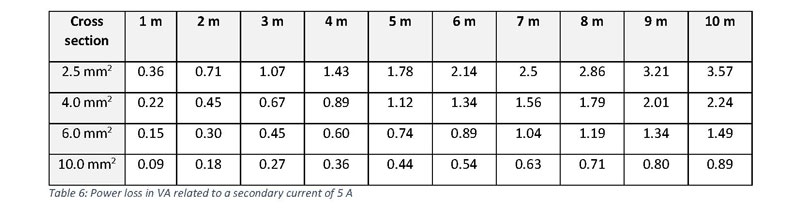
In the case of current transformers, a transformer with a 5 A output and a small burden should be selected if there is a risk of under burdening. With the connection cable, an additional burden can be created relatively easily (〖P=I〗^2×R), to get over 25 percent of the rated power.
The following formula must be used to calculate the self-consumption of copper lines.
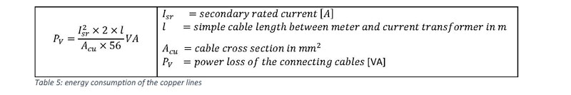
For a quick overview, the following table shows the power losses in VA with a secondary current of 5 A depending on the length and the copper cross-section of the connection cable.
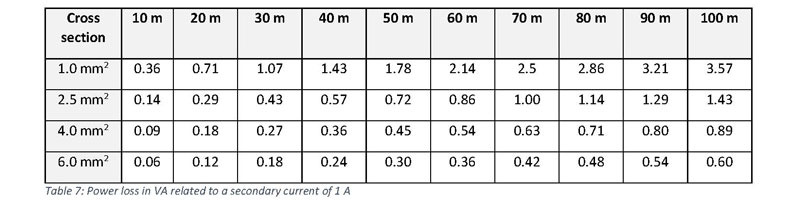
The following table provides information for the 1 A current transformers.
The correct burden in conjunction with the measurement protocol of the instrument transformer manufacturer enables a very precise current measurement to be implemented. In consultation with the manufacturer, the fault line can also be optimized for the expected load with the voltage transformer.