Influence of the transformer phase error on the calculation measurement
The quality of the billing measurement of electrical energy is not only determined by the percentage amplitude error of current and voltage transformers (1).
current and voltage transformers (1). The correct temporal transfer of the current and voltage signals (phase error) of the transformers used is also
phase error of the transformers used is also important for high-quality energy measurement. How the phase error of the transformers used
The effect of the phase error of the transformers used on the energy measurement will be analysed below.
Current transformer
The phase difference between the primary and secondary vectors is zero for the perfect converter. The phase shift
is described as positive if the secondary vector leads the primary vector. The phase error for inductive current transformers is
usually specified in minutes. The valid accuracy classes of current transformers of the relevant DIN EN 61869-2 are defined as follows.

The S classes are even more restrictive in terms of the permitted phase and ratio errors and at the same time have been extended by the
1 per cent of the rated current.

The following figure shows the phase errors for an inductive current transformer in class 0.5 S with a modulation of 1 to 150 per cent of the rated current.
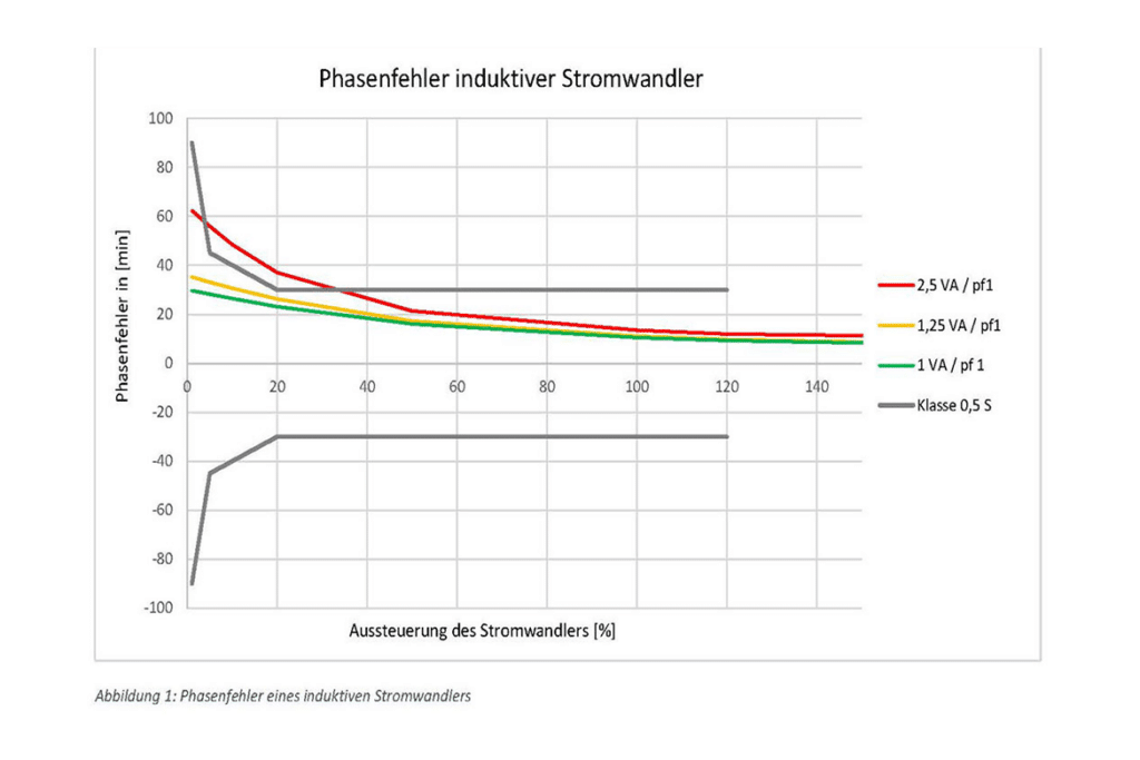
It can be seen that the converter does not fulfil the 0.5S class at 2.5 VA. The class is only fulfilled from 1.25 VA.
In order to get a feel for the effects of energy measurement, the question arises as to what extent the time offset of the primary variables current and voltage can influence the effects of the phase error of the current transformer.
the effects of the phase error of the current transformer on the active power measurement.
active power measurement. Ideally, both current and voltage are sinusoidal oscillations. It is
It is suspected that it is not insignificant if the current to be measured leads or lags the voltage.
Ultimately, the phase offset of current and voltage in the electrical supply system is characterised by the so-called
power factor. If the supply voltage is assumed to be constant, the connected load determines the
power consumed and therefore the phase angle of the current.
The power factor is the ratio of the amount of active power ?? to the apparent power ?? and, in the case of sinusoidal quantities, indicates the phase angle of the current via the
decimalised number scale from 0 to 1 and indicates the trigonometric ratio between the active power and the apparent power. (3)(4)

For sinusoidal currents and voltages, the effective factor is also defined by the ratio ??⁄?? It is equal to the cosine
of the phase shift angle φ

The representation in the complex plane illustrates the relationships.
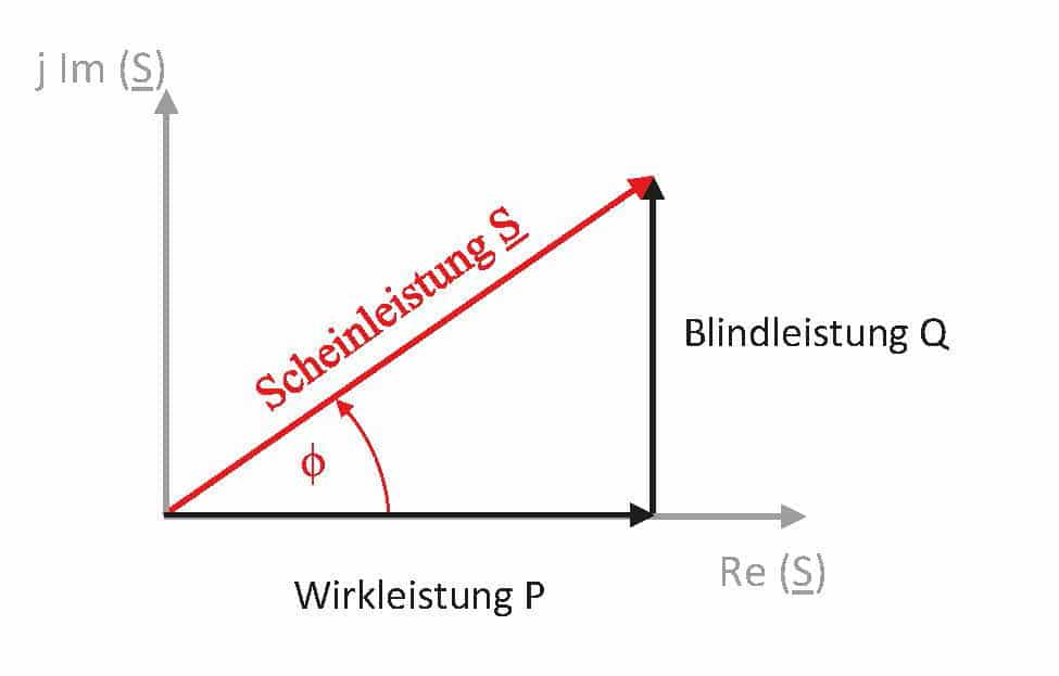
Figure 2: Power vector diagram and phase shift angle for sinusoidal voltages and currents in the complex plane
The following diagram clearly shows that, due to the cosine function, there is no linear relationship between the phase shift and the resulting effect factor.
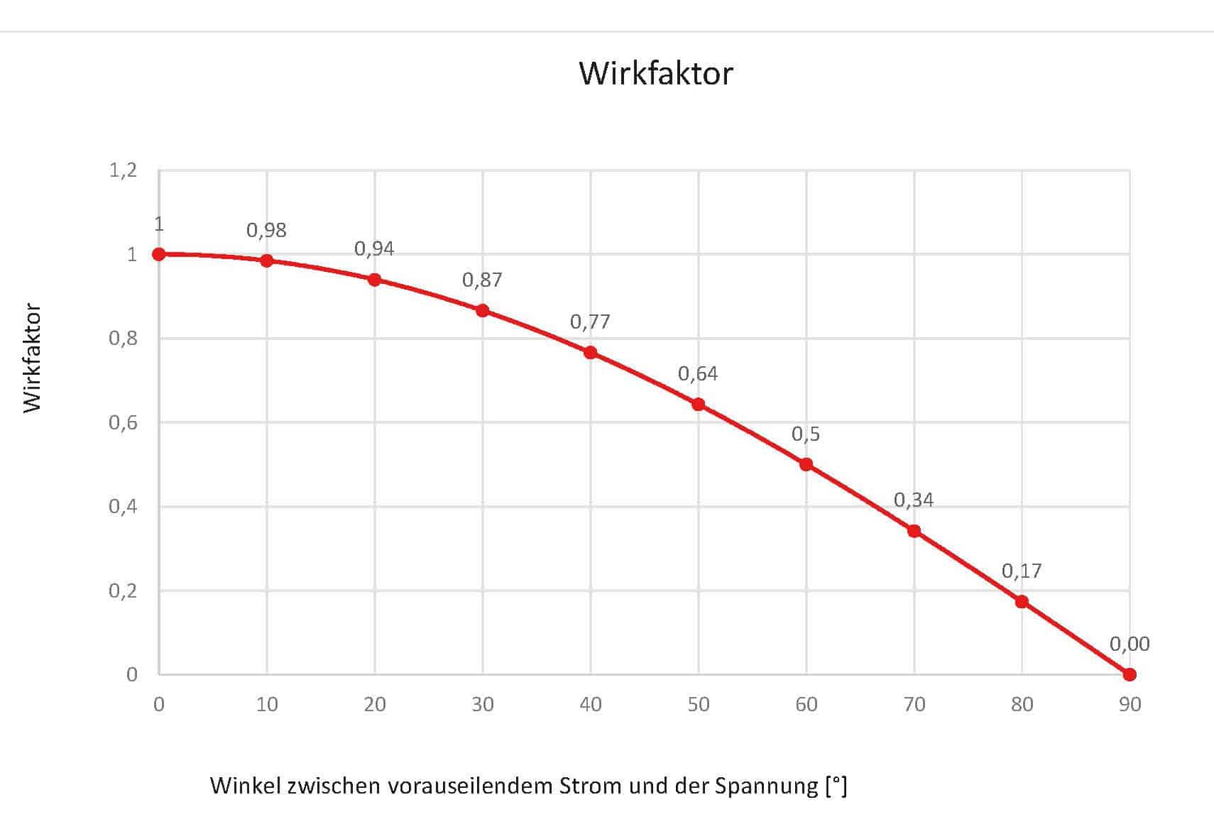
The above assumption can therefore be answered unequivocally. The influence of the current transformer phase error on the
energy measurement depends on the phase offset between the two primary variables current and voltage. The phase error
of the current transformer accordingly leads to an increase in the power factor error depending on the point on the curve.
Let us first assume that the two primary variables have no phase offset. This results in a
power factor of 1.
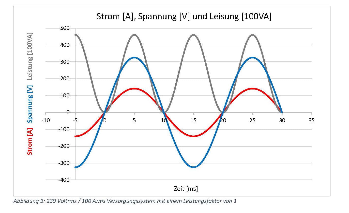
If there is now a phase offset between the current and voltage signal on the secondary side due to the phase error of the current transformer, the power curve calculated in the
secondary side, the power curve calculated in the meter will show negative components. In addition to the active power,
reactive power is measured.
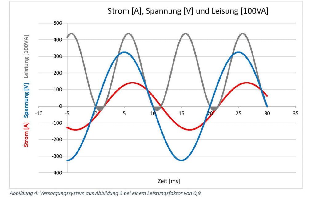
In the figure above, the current lags behind the voltage. At 0, 10 and 20 ms on the time axis, the respective reactive power
reactive power components are coloured grey. The effective value of the active power has decreased. The following diagram provides information about the percentage reduction in active power in relation to the current transformer phase error.
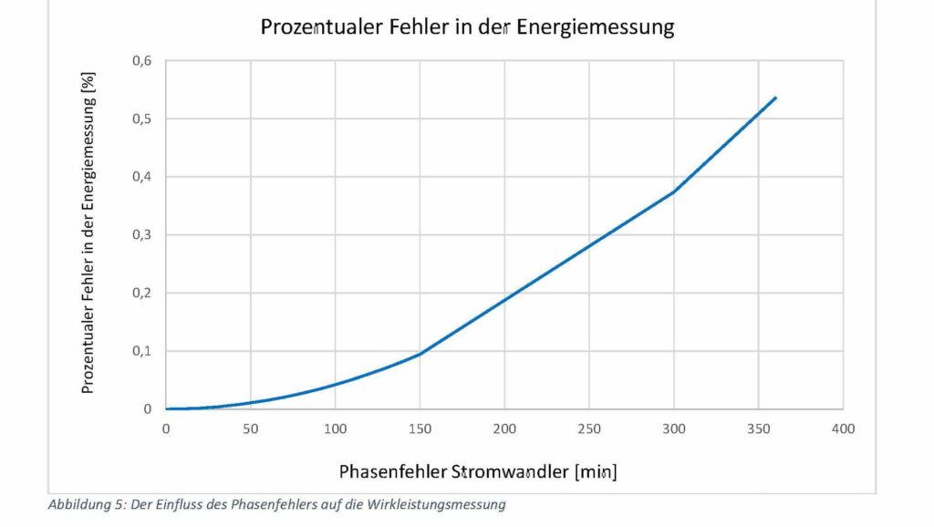
It is clearly recognisable that a phase error of the current transformer under 50 minutes has only a minor influence on the energy measurement. At 360 minutes, i.e. 6 degrees, the influence is somewhat greater. Here, the percentage error in the energy
the energy measurement is 0.54 per cent.
The exact values for common error limits are listed in the following table.

In practice, however, the power factor is often not equal to 1 and lies between 0.9 and 1.
transformers, power factors as low as 0.1 can be achieved. The following diagram provides information on the influence of the phase error on the active power measurement as a function of the power factor.
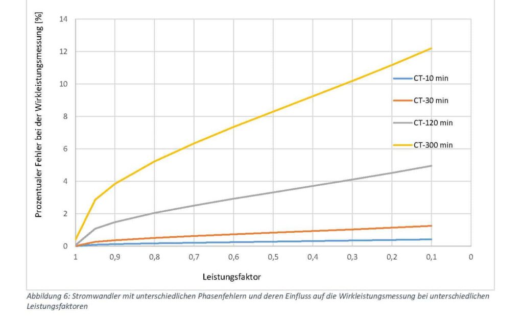
Obviously, the percentage error caused by the phase error of the current transformer increases significantly in the active power measurement in a system with a larger phase offset (smaller active factor).
in a system with a larger phase offset (smaller effective factor). The current and voltage curves are assumed to be sinusoidal
oscillation.
However, as the current curves in practice often contain a high proportion of harmonics, the curves are usually significantly
distorted and sometimes have steep slopes. It is likely that non-sinusoidal curves as well as the power factor
influence the effect of the current transformer phase error. In order to investigate this issue in more detail, the following
example, the following curve is assumed.
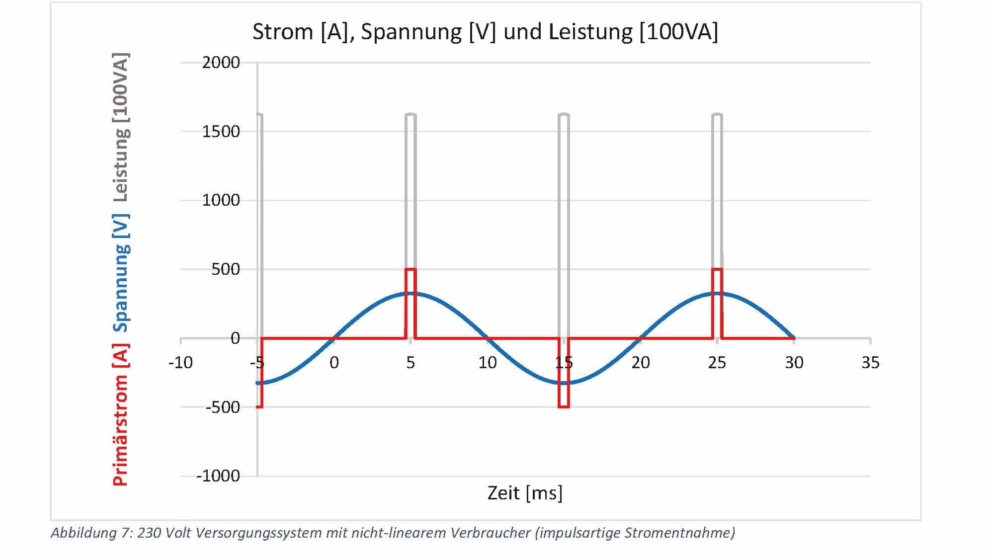
Assuming that the current transformer can transmit all harmonics, the following diagram results for the various current transformer phase errors the following diagram results.
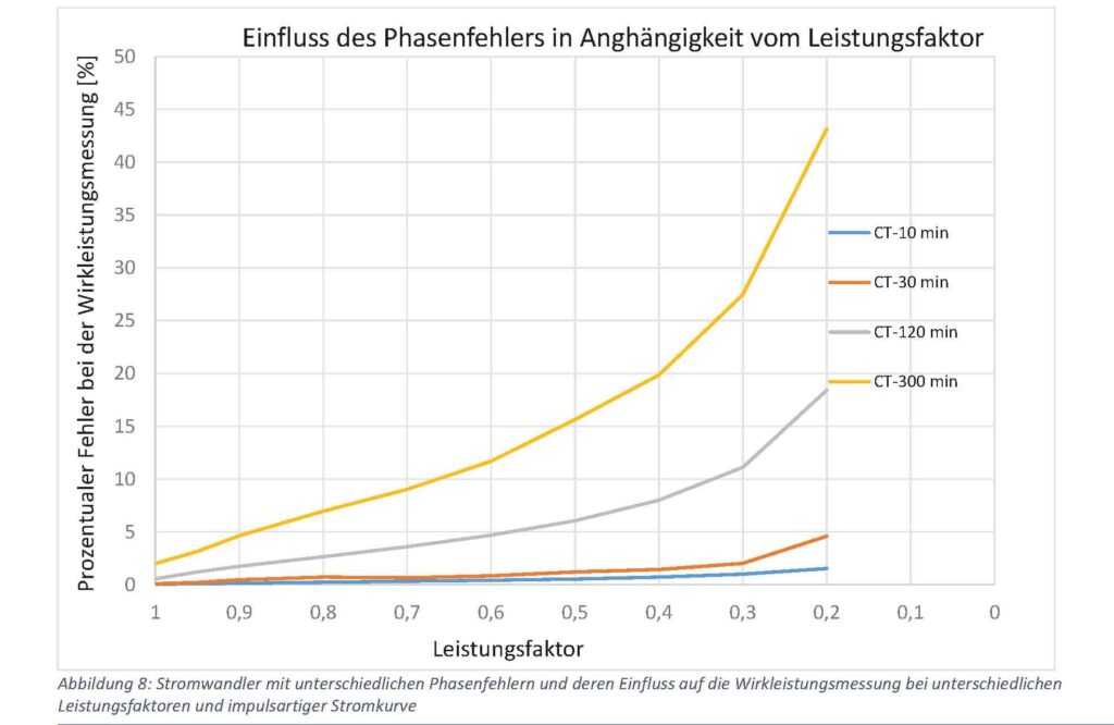
It can be concluded that not only the power factor of the electrical supply system has a significant influence on the effects of the current transformer phase
the effects of the current transformer phase error on the active power measurement. The waveform of the primary current
current signal can also have an effect on the accuracy of the active power measurement. For current transformers up to class 0.5, there are
current transformers up to class 0.5, there are apparently moderate errors in the power factor range from 1 to 0.9.
phase error already causes an error in the active power measurement of 0.46 % at a power factor of 0.9.
active power, however, considerable amounts can be incurred.
It can be stated that the current transformer for billing measurements should always have a low phase error
phase error, as the power factor and the actual current curves are often not known
Voltage transformer
The secondary signal of the voltage transformer can also have a phase error. The following table shows the measurement classes of DIN EN 61869-3.

As the voltage can be assumed to be almost constant compared to the current in supply networks, the classes
only apply to 80 to 120 per cent of the nominal voltage. A typical fault diagram illustrates the situation.
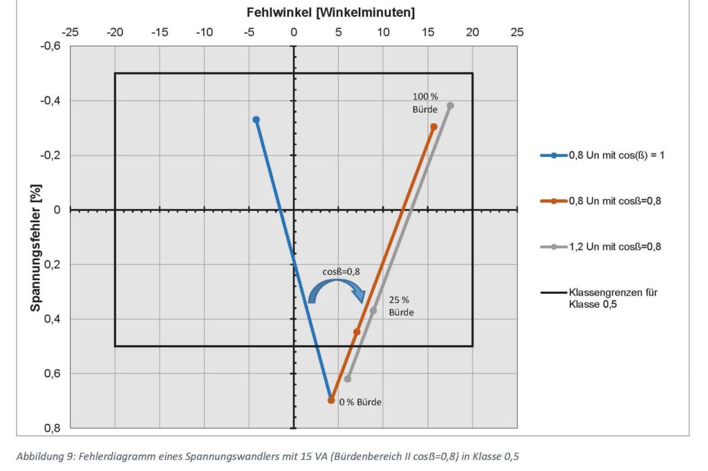
With a purely ohmic load on the voltage transformer, the phase error on the blue line is between 5 and
-5 angular minutes. With a resistive-inductive load (cosẞ = 0.8), which is provided in load range 2, the phase errors
(orange and grey straight line) range from approx. 4 to 18 minutes depending on the load (0 to 15 VA). If the current and voltage transformers have a
have a positive phase error, the phase offset between the two signals is reduced. However, if the energy supply of the
meter is provided by the voltage transformer, capacitive loads usually result. According to DIN EN
61869-3 and also increase the phase offset between the current and voltage signal. The active power calculated in the
active power calculated in the meter thus experiences an undesirably large deviation.
