Condition-based periodic inspection for fixed installations in accordance with DGUV V3
Differential current monitoring
A system test was already required in the first VDE regulation from 1896.
The system test for new and extended systems is now described in DIN VDE 0100-600.
Periodic inspections are standardised in DIN VDE 0105-100/A1 with references to DIN VDE 0100-600.
In addition, periodic testing is also described and required in the DGUV regulation 3 (formerly BGV A3).
The abbreviation DGUV stands for the German Social Accident Insurance. This association consists of 27 accident insurance funds and nine industrial employers’ liability insurance associations. It currently insures around 70 million people against the consequences of accidents at work and occupational illnesses. Regulation 3 of the DGUV describes the testing of electrical equipment and systems used in companies.
The intention of this regulation is to ensure that the systems are in a proper condition. This minimises the risk of personal accidents, electrically ignited fires or system damage.
As the DGUV-V3 test is a statutory requirement, companies are obliged to carry out this test. Insurance companies regularly refuse to pay benefits in the event of damage if there is no proof that the equipment causing the damage has been inspected within the prescribed period. Even the cancellation of policies is not uncommon in serious cases. In addition to the losses and costs, the company may also face lawsuits for damages that could jeopardise its existence.
As understandable as this regulation may seem, it not only causes considerable costs for the operators of electrical systems and stationary machines.
The systems and machines are often switched off for the test in order to carry out the insulation measurement or to test the protective devices, e.g. RCDs. The intervals for periodic testing are listed in DGUV Regulation 3 in Table 1A.
One question that is often discussed in practice is whether the specified inspection intervals are legal requirements or merely guidelines.
IDGUV Regulation 3 states verbatim under § 5 Inspections: “The employer must ensure that the electrical systems and equipment are inspected to ensure that they are in proper condition
1. before initial commissioning and after modification or maintenance before recommissioning by a qualified electrician or under the direction and supervision of a qualified electrician and
2. at certain Intervall.
The deadlines must be set in such a way that any defects that are likely to occur are detected in good time.”
Inspection intervals often only recommended
According to the BG ETEM [2], Table 1A of DGUV Regulation 3 refers to guideline values that have been established over the years. The proven inspection intervals are also often only recommended in the German Workplace Ordinance (ArbStättV).
![Tafel 1. Wiederholungsprüfungen ortsfester elektrischer Anlagen undBetriebsmittel (Richtwerte nach Tabelle 1A, DGUV-Vorschrift 3) [1]](https://mbs-ag.com/en/wp-content/uploads/sites/2/2024/07/Tabelle_1_Richtwerte-nach-DGVU-1024x522.jpg)
7 steps of the periodic inspection in accordance with DGUV V3:
- Visual inspection
- Testing of PE protective conductor and potential equalisation
- Insulation test (can be omitted with residual current monitoring in accordance with DIN 62020)
- Testing the switch-off conditions
- Testing the protective devices
- Earthing measurement
- Test report
The question now arises as to the basis on which the inspection intervals for fixed installations should be calculated if the values in Table 1 are merely guidelines. Any deviation from the proposed inspection intervals should be justifiable if necessary. There are no references in DGUV Regulation 3. There have been no changes to this regulation since it was published in 1979.
The much more recent DGUV information 203-071 [3] (issue date 2020.01) is helpful. It states under point 7 “Inspection intervals”: “The determination of the inspection intervals as part of the risk assessment is the responsibility of the employer. The risk assessment must be carried out professionally … Inspection intervals must be determined taking into account the specific operational situation when operating the systems and equipment and specified in the respective risk assessment. …
The recommendations in the implementation instructions for Section 5 of DGUV Regulations 3 and 4 can be used as a decision-making aid for determining inspection intervals. These values are guide values for normal operating and environmental conditions and are for guidance only. An unchecked adoption of the suggested inspection intervals without taking into account your own operational situation can lead to dangerous defects not being detected in time if the inspection intervals are too long. …” Below this text is the already familiar note from DGUV Regulation 3:
“Inspection deadlines are not optional deadlines! The deadlines must be set in such a way that any defects that are likely to occur are detected in good time. (§ 5, Para. 1, 2 DGUV Regulation 3 and
4).” The chapter concludes with the following statement: “This requirement may mean that the actual inspection periods must be significantly shortened or extended compared to the guideline values in the tables, depending on the operational situation.”
According to the above, the basis for the inspection intervals to be determined is a risk assessment in accordance with TRBS 1111 [4]. It is certainly possible to determine inspection intervals that exceed the suggested four years.
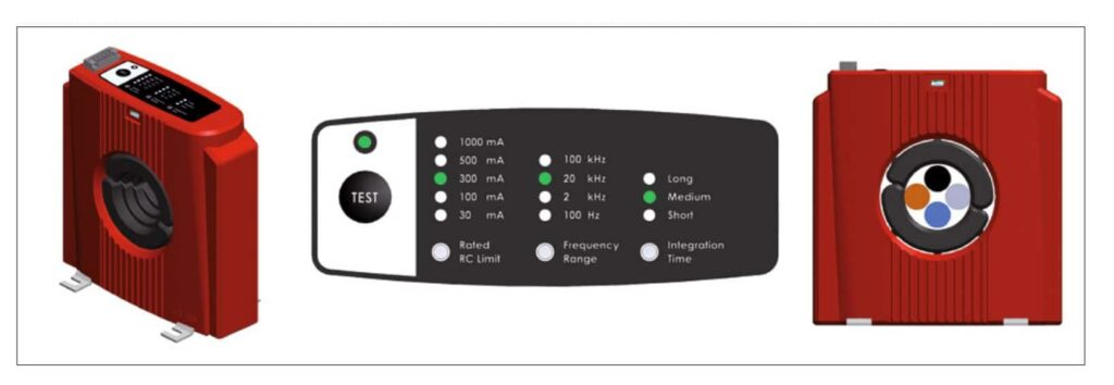
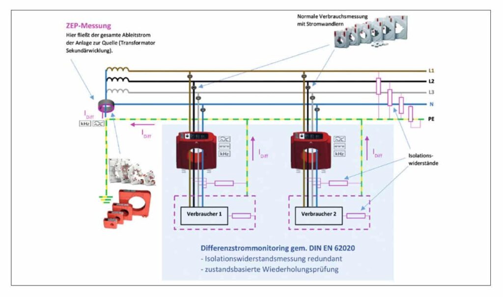
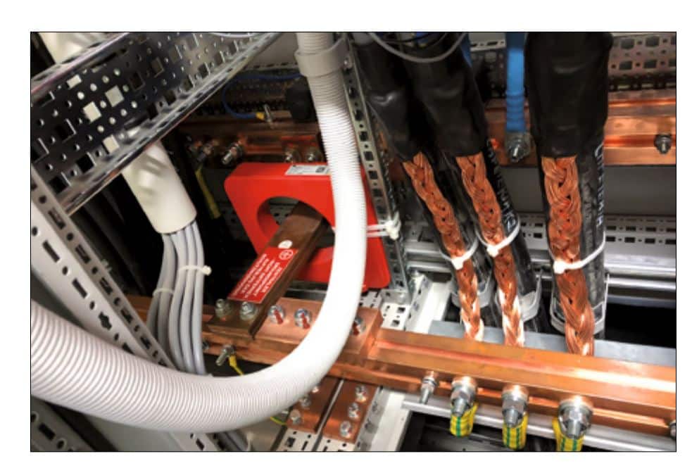
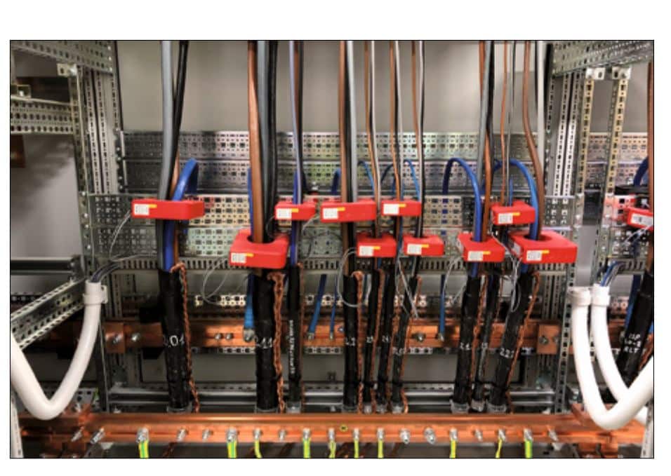
Figure 4: ZEP measurement (left) and residual current measurement of the individual outgoing circuits (right)
This is therefore permissible according to the DGUV regulations. Despite the fact that the inspection period for the periodic inspection is set in accordance with the regulations, the system or machine may fail due to unforeseeable circumstances. To counteract this scenario, predictive maintenance is already being practised in some innovative industrial sectors and critical properties. The inspection or maintenance times of a machine or system can be precisely predicted on the basis of condition data obtained from sensors.
Detect unforeseen damage in the insulation
In the area of electrical installations, unforeseen damage to the insulation can be detected in good time with continuous residual current measurement. This means that repeat testing can be brought forward in the event of increased residual current values. In most cases, this can prevent an uncontrolled shutdown of the system. Continuous residual current measurement is already mandatory for the construction of new data centres (DIN EN 50600-2-2). The residual current is used as a characteristic value for the condition of the system’s insulation. In a recent project, the operator was able to detect faulty switched-mode power supply units at an early stage via increased residual current levels and replace them in good time. This prevented an uncontrolled shutdown of various servers.
A welcome side effect is that testing the insulation in accordance with DGUV regulation 3 can be omitted. This is documented in DIN VDE 0105-100/A1:06/19. Section 5.3.3.101.0.2 states: “If a circuit is continuously monitored by a residual current monitoring device in accordance with DIN 62020 (VDE 0663) … and these monitoring devices function properly, the measurement of the insulation resistance can be omitted.”
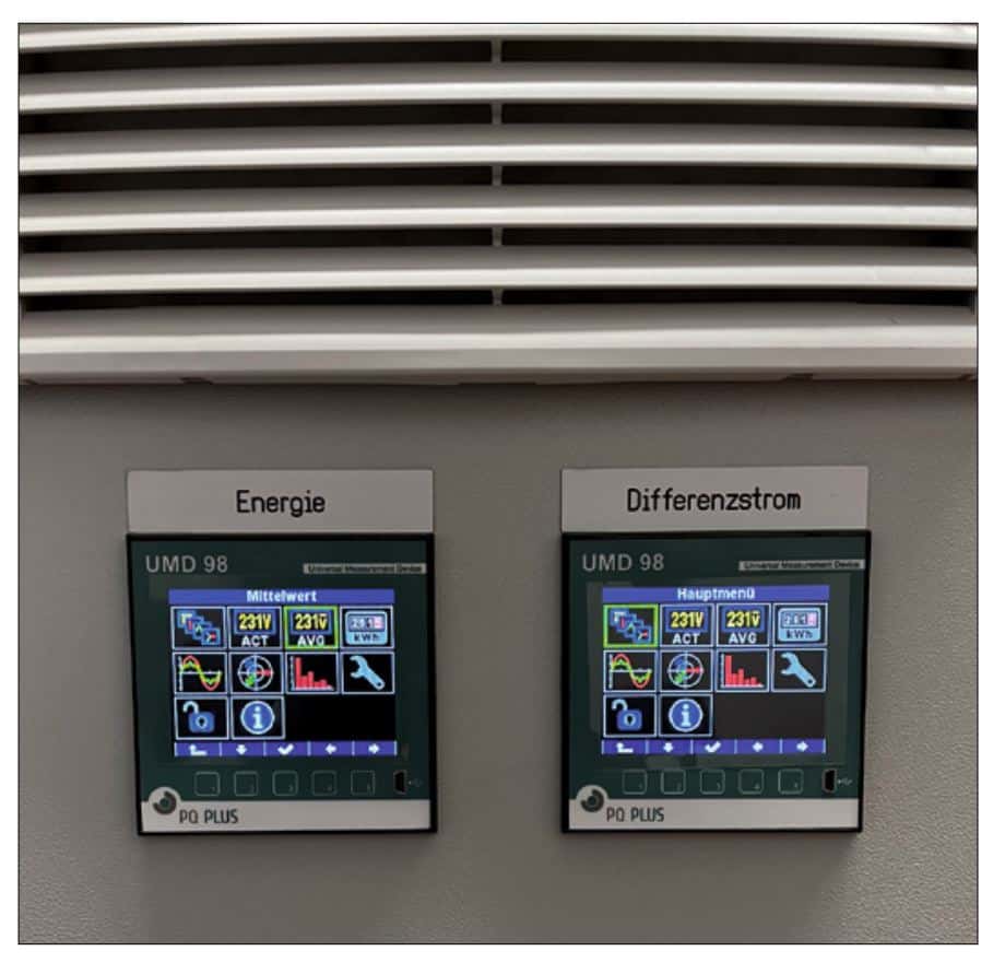
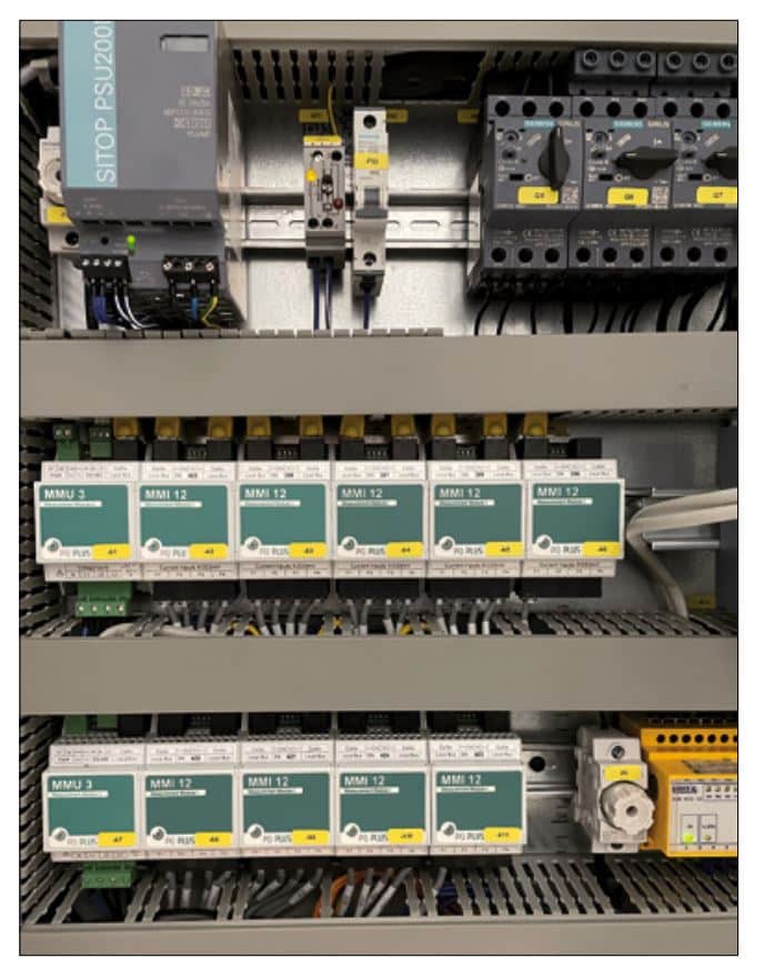
Figure 5: Installation of the measuring devices
Conventional insulation measurement is often very time-consuming. In some cases, system components such as frequency converters or switching power supplies have to be disconnected because the sensitive semiconductor components can be damaged by the test voltages [5]. The first DGUV-V3 testing institutes are already using residual current monitoring in various industrial sectors. By analysing the measured values of the residual current recorded in databases, it is possible to shorten the test period for the periodic test in accordance with the risk assessment if necessary. Various alarm thresholds trigger notifications by text message or e-mail.
The system is thus subjected to continuous monitoring, whereas the conventional insulation resistance test only provides a snapshot.
If the system does not have a protective device to be tested, in some cases it is even possible to dispense with the switch-off completely.
Significant progress in terms of system monitoring
In addition to some DGUV testing institutes, more and more energy management providers are also offering continuous system monitoring by means of residual current measurement. The repeat test can then be brought forward if necessary and an uncontrolled shutdown can often be prevented. For many companies, this represents significant progress in terms of system monitoring, system shutdown and costs.
If switched-mode power supply units or frequency converters are installed in the systems, it must be ensured that residual currents can consist of DC and AC components. Corresponding RCDs of type B+ can already protect all of these non-linear loads. Not only DC components are detected, but AC components up to 20 kHz can also be processed. If a residual current monitor in accordance with DIN EN 62020 is used with these loads, this device should also be able to measure DC currents and AC currents up to at least 20 kHz.
MBS AG offers the new RCMB 70 residual current monitor for this range (Fig. 2), which can even calculate the TRMS value up to 100 kHz. In addition to a relay output with variable trigger thresholds, the measured value is output as a 4 mA to 20 mA DC standard signal. This ensures connection to universal measuring devices with significantly lower sampling rates or fieldbus systems.
In addition to the individual outgoing circuits, the central earthing point ZEP can also be monitored (Fig. 3). This value can be used to assess the insulation of the entire system.
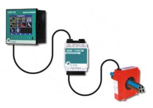
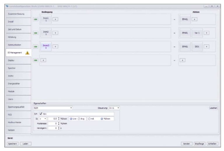
The following is an examination of installations in practice. In this project, the residual current transformers were connected to universal measuring devices from PQ Plus. Using optional modules (MMI 12RCM), each with twelve additional inputs for residual current sensors, it was possible to realise an optimum and compact residual current monitoring system for the customer (Fig. 4, 5). The residual currents can be viewed via the software and linked to alarm thresholds. The system operator and the DGUVV3 testing institute are sent an e-mail if the residual current levels increase. The alarm thresholds can be set using the free Envis software from PQ Plus depending on the values actually measured (Figure 6). Future system monitoring solutions often require the co-operation of several people from different companies and departments. It is always important to take the needs of each specialised discipline seriously and to understand them. Only in this way can watertight safety concepts be developed in the manner of German officials and at the same time the immense advantages of automation be optimally utilised.
The motto “No risk, no fun!” continues to apply for companies that want to completely avoid repeat inspections in accordance with DGUV V3 in the future.
Literature
[1] https://www.bgw-online.de/
SharedDocs/Downloads/DE/
Medientypen/DGUV_
vorschrift-regel/DGUVVorschrift3_Unfallverhue
tungsvorschrift-elektrAnlagen-Betriebsmittel-bf_
Download.pdf?__blob=
publicationFile
[2] https://www.bgetem.de
[3] https://publikationen.dguv.de/
widgets/pdf/download/
article/787
[4] Technische Regeln für Betriebssicherheit, Gefährdungsbeurteilung, TRBS 1111 (Ausgabe: März 2018) https://
www.baua.de/DE/Angebote/
Rechtstexte-und-Technische-Regeln/Regelwerk/
TRBS/pdf/TRBS-1111.pdf?__
blob=publicationFile
[5] https://www.schutztechnik.
com/posts/differenzstrommonitoring-in-der-industrie
Authors R. Bürger MBS AG and K. Behringer PQ Plus
